 |
||||||||||||
| Home |
|
Products For Sale |
FAQs, Tips, Manuals |
Referral List |
|
Photo Gallery |
|
Links |
|
Contact Us |
|
|
||||||||||||||||||
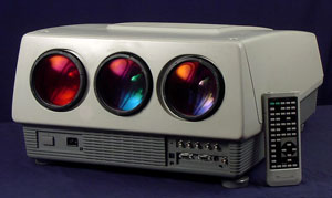
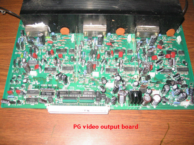
Video Output Board The below images show the PG series of video output boards. The PG + and PG Xtra used slightly different looking boards with the video output chips being located on the CRT sockets instead of on the board itself.
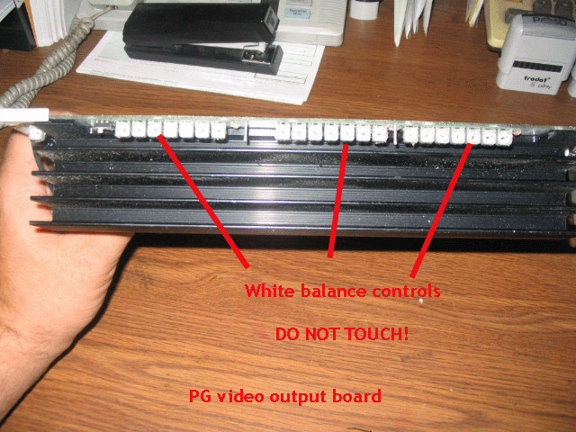
Again, there are a number of trimpots located on the video output board, and it’s very tempting to tweak and turn these pots to ‘make the color look better’. Trust me, don’t do it. Unless you have a colorimeter and an oscilloscope, don’t touch these controls. The NEC service manual is very poorly written with regards to aligning these pots, and the adjustments are tricky. This board is located under the metal shield that has the fan on it near the back of the set. The later PG Xtras did not have a large heat sink on this board as the video output chips were on the CRT sockets. Note that the leads connecting this board to the CRT socket are VERY tight, and easily pull out of the PC board sockets when this board is disturbed. That can cause a dead tube or one with weak light output. If you dare work on this board and then have tubes that won’t light, check the wiring to this video output board. I have not taken pictures of the video driver board or the video input board.
Again, these have no serviceable parts on them, and generally do not fail. The
video/s-video input board is located under the video board shield, and is
located closest to the back of the set. The 6PG series sets did not include this
board, it was an option. Therefore, even though the video and S- video jacks are
on the front of the 6 PG units, chances are they are dead, as they will not work
unless the video board is installed.
|
|
|||||||||||||||||
 NEC PG Series
© Copyright CurtPalme.com. All Rights Reserved. |