 |
||||||||||||
| Home |
|
Products For Sale |
FAQs, Tips, Manuals |
Referral List |
|
Photo Gallery |
|
Links |
|
Contact Us |
|
|
|||||||||||||||||
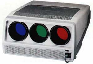
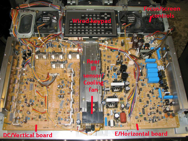
All pictures below came from a 1272, the latest model. The top cover insert around the built in wired keypad comes off with two screws. Slide the cover towards the back of the set once the screws are loose, and it will lift right out. Depending on which 12XX set you have, the top clamshell half of the case then comes loose by taking out or loosening two more screws around the keypad and depending on the model, the top cover is held to the front lens frame by 4 clips or screws. Taking off the top cover gives you the below view:
Note that the Sony has very little adjustments with internal trimpots unlike other sets out there. Most of this information will be for identification purposes only. Don’t turn any internal trimpots on these Sonys unless you know what they are for! The DC or vertical board contains all of the vertical output and convergence output circuits for each CRT. There are no user adjustments on this board. The three small V yoke connectors are located at the top of the board closest to the CRT’s, and need to be changed over to the alternate connectors on the board to flip the image vertically. The E or H output board contains the horizontal output section for the projector and also does not have any adjustments on it. The H yoke connectors are located in the upper right hand corner and also need to be flipped and inserted onto the alternate connectors to flip the image in an H direction. Under the back IR sensor PC board is a small fan to cool the middle heat sink. This fan suffers from dry bearings and can screech or grind. The cure is to pull off the paper sticker which will expose the back bearing. Shoot the bearing with a tiny shot of WD-40 or silicone based lubricant and the fan will usually quiet down. The wired keypad is identical to the wireless one, but has the IR emitter and
associated parts removed. Some people have added these components to turn the
wired remote into a wireless one, but it’s easier to find a good used remote on
eBay
|
|
||||||||||||||||
 Sony 125x/127x
© Copyright CurtPalme.com. All Rights Reserved. |