CurtPalme.com Home Theater sales, calibration, service, and discussion forum. Hundreds of free manuals & setup tips.


Sign up and receive the latest newsletters by email!     Join the Forum discussions!    
    Site Map  
Home Products
For Sale
Referral
List
Photo
Gallery
Links Contact
Us
CRT Primer
Troubleshooting Tips
Mounting Methods
Definitive CRT
Projector Setup Guide
Tube/Raster Setup
Tube Condition (Wear)
Advanced Procedures
Projector
Specifications
Projector Rankings
Video Processors
Ampro 1500/2000
Ampro 2300/2600
Ampro 3600/4600
Barco (Older Analog)
Barco 70x/Cine7  
Barco 500/800/801
Barco 808/Cine8
Barco 120x/Cine9
Dwin 500/700
Electrohome ECP 
Electrohome Marquee 
Mitsubishi
NEC PG
Panasonic 108x
Runco
Seleco
Sony 10xx
Sony 125x/127x
Sony 1292
Sony D50
Sony G70
Sony G90
Zenith 841/851
Zenith 895/900
Zenith 1200


NEC XG Series

      >> Introduction
      >> Layout and Setup Tips 
      >> XG Models and Production Run Dates
      >> Multi Default Frequencies IMMS
      >> Hidden Control Functions
      >> PC Control Cable Pinout & Software
      >> Lens Focus Fix (LC Units)
      >> Misconvergence During Switching Fix
      >> Compatibility of PC Control Versions
      >> Incorrect Lens Focus & Halos Fix
      >> Manuals / Downloads


Layout and Setup Tips

 (Page 1)

Page: 1 2 3 4 5 6


The NEC XG projector has far fewer user adjustments internally as any number of other projectors. This is because many adjustments made via trimpots in other sets are done in the menus on the NEC XG. The big note attached to the XG projector is: READ THE MANUAL! 

If you go into the NEC projector at random and attempt to adjust settings that you have not read about in the manual, and more importantly, don’t have a full understanding of what the control does, you stand a very good chance of having to send the projector to a service tech for recalibration.

If you don’t understand the manual, ask. The NEC manual, especially the service manual, can be difficult to understand. Ask before tweaking!

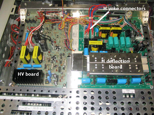
The above picture shows the two main boards that are located under the top cover. The left board is the HV board and the right board is the H deflection board. The left board has no user adjustments on it as they are sealed, and you need a 35 Kv HV probe to recalibrate the board if any work is done on it. The right board has one user adjustable trimpot on it, the master H width control that may be adjusted if the menu amplitude control doesn’t give enough width to the image.

Here's how to adjust the H width control: (you'll need a DC voltmeter and the knowledge of using it).

Using a 480i video signal (composite or s-video):

1) Take Horizontal Amplitude (width) to maximum on the remote....
2) Adjust VR5301 for 4.5+/-.05 VDCat Pin 1 of IC5306
3) Then connect multimeter to ground and + lead to TP5302 and adjust VR5302 for 7.5 +/- .1 VDC
4) Then recheck VR5301

The H deflection board also has the H yoke connectors on it that must be changed as per the sticker next to the H board to change the set from floor to ceiling mount.

The boards under the metal shield are identified by the sticker on the plate. These are the video and CPU/processing boards crucial to the proper operation of the set. With the exception of the controls listed below, consider these boards to be off limits to tweaking. An actual failure of these boards are rare, but can occur. More info listed in the pages that follow ...


Next Page ...


© Copyright CurtPalme.com. All Rights Reserved.