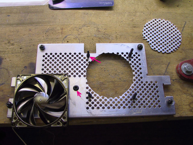
5. Drill the upper left rubber hole with a 4mm diameter drill bit and the
fan's wire pass-through hole with a 5mm diameter bit. Use a rubber grommet to
protect the cable and place the four rubber spacers within the grid:
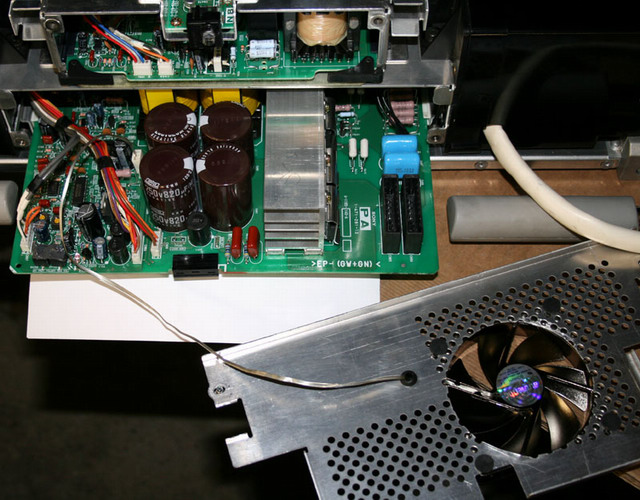
6. Place the fan on the rubber spacers and place the fan wires through the grid
plate:
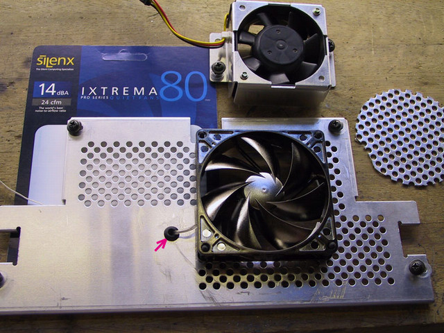
7.
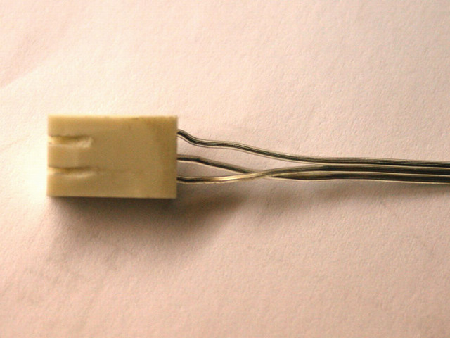
At this stage, update the SilenX white connector housing wiring and shape it to
fit the PA board connector by swapping the +12V and SENSE (French for
"Rotation") wires inside the
housing to correspond to the Sony wiring:

Turn the fan connector upside down and cut the two tables on the SilenX white
connector housing with a cutter. With a small metal saw, make two slots in the
white plastic housing:
Connect the SilenX connector to the PA board connector as shown:
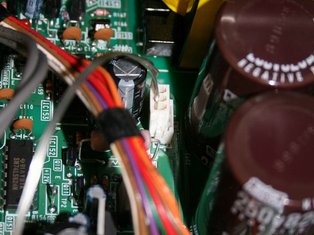
Then reconnect all the others connectors back in their place:

|

