| Author |
Message |
Ile
Joined: 09 Mar 2006
Posts: 1491
Location: Jyväskylä, Finland
|
| Posted: Tue Aug 28, 2007 5:27 pm Post subject: Poor mans lens flapping to Barco 1200/1209 |
|
|
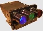
These projectors don't have lens flapping (bellows) and LC hardwares are glued to tubes equally (almost) in factory, they used 1.3-1.5 mm thick leaky rtv seam.
I have LC hardwares removed from my tubes and I'm wondering should I glue them back so I take calculated Scheimpflug corrections into consideration. That would give more even focus and fine adjustment could be done adding thin washers under lens.
Here is my calculated rtv seam thicknesses to tube corners in mm, these are calculated for 2 m wide picture and 10.5 projection angle.
1.0 1.7
[R]
2.6 3.3
1.0 1.0
[G]
2.6 2.6
1.7 1.0
[B]
3.3 2.6
Bottom corners are going to have pretty thick rtv seam, I hope those last. 
Anybody tested this?
|
|
| Back to top |
|
 |
Joust

Joined: 05 May 2006
Posts: 2429
Location: Almonte, Ontario, Canada
TV/Projector: Marquee 8501LC
|
| Posted: Tue Aug 28, 2007 9:26 pm Post subject: |
|
|
sounds logical.
if it doesn't work its just a lot of RTV cutting and try again so it not much of a gamble.
go for it.
|
|
| Back to top |
|
|
Ile
Joined: 09 Mar 2006
Posts: 1491
Location: Jyväskylä, Finland
|
| Posted: Wed Sep 26, 2007 6:26 pm Post subject: Re: Poor mans lens flapping to Barco 1200/1209 |
|
|
| Ile wrote: | Here is my calculated rtv seam thicknesses to tube corners in mm, these are calculated for 2 m wide picture and 10.5 projection angle.
1.0 1.7
[R]
2.6 3.3
1.0 1.0
[G]
2.6 2.6
1.7 1.0
[B]
3.3 2.6
|
Yesterday I made 3x3 mm plastic peaces (above thicknesses) and glued those to each corner of the tube, using rtv. Today I glued tubes to LC hardwares.
|
|
| Back to top |
|
|
lucht
Guest
|
| Posted: Tue Dec 18, 2007 3:14 pm Post subject: Re: Poor mans lens flapping to Barco 1200/1209 |
|
|
Hi Ile,
How do you calculate these schiempflug corrections, because inside the PT18-244 LC housings there are 4 small plastic distance holders which I can use.
I am converting my both BD808s with 120 Mhz RGB amps in LC Versions with PT18-244 with fixed LC-Housing and HD18 Lens. Similar to the modification from Chuchuf, only with LC-Housings without Schiempflug http://archive2.avsforum.com/avs-vb/showthread.php?p=7554772
I will also convert one of my BD801s to LC mit 07MPSA and HD117.24 lens
Thanks
Wil
|
|
| Back to top |
|
|
Ile
Joined: 09 Mar 2006
Posts: 1491
Location: Jyväskylä, Finland
|
| Posted: Tue Dec 18, 2007 3:50 pm Post subject: |
|
|
I made small plastic spacers and glued those to tube.
Barco lens software calculates needed vertical and horizontal Sheimpflug (mm and angle) to text sheet.
Just input correct AR, projection angle and -distance...
http://www.dvdplaza.fi/forums/attachment.php?attachmentid=3801&d=1095853469
Using angle and precise tube face dimensions might give more accurate results than those mm values. I believe those mm readings are calculated for lens screw positions that might be little different what tube corners.
Then you can do fine tuning using thin washers or o-rings between c element assembly and lens.
|
|
| Back to top |
|
|
r.bauer
Joined: 08 Apr 2006
Posts: 280
Location: The Netherlands
|
| Posted: Tue Dec 18, 2007 4:58 pm Post subject: |
|
|
The tubes in a standard 1200, 1209 or 1209/2 already have a 'fixed' amount of scheimpflug correction when they leave the factory. I have set up many of these projectors mostly on 2.4m wide screens, and all of them had perfect corner focus in all 4 corners. I assume that the factory fiexed scheimpflug correction is for this screen size.
Did you really have such a bad corner focus, or did you use non-standard scheimpflug correction tubes from a simulator?
But good job for trying 
|
|
| Back to top |
|
|
lucht
Guest
|
| Posted: Tue Dec 18, 2007 5:19 pm Post subject: |
|
|
| Ile wrote: | I made small plastic spacers and glued those to tube.
Barco lens software calculates needed vertical and horizontal Sheimpflug (mm and angle) to text sheet.
Just input correct AR, projection angle and -distance...
http://www.dvdplaza.fi/forums/attachment.php?attachmentid=3801&d=1095853469
Using angle and precise tube face dimensions might give more accurate results than those mm values. I believe those mm readings are calculated for lens screw positions that might be little different what tube corners.
Then you can do fine tuning using thin washers or o-rings between c element assembly and lens. |
Ahaa so, you recalcutate the 0,62 degree Vert. back from the screws to the corners of the tube, that explain the 1,6 mm in place from the 2,5 mm.
Thanks
Wil
|
|
| Back to top |
|
|
Ile
Joined: 09 Mar 2006
Posts: 1491
Location: Jyväskylä, Finland
|
| Posted: Tue Dec 18, 2007 8:23 pm Post subject: |
|
|
| r.bauer wrote: | The tubes in a standard 1200, 1209 or 1209/2 already have a 'fixed' amount of scheimpflug correction when they leave the factory. I have set up many of these projectors mostly on 2.4m wide screens, and all of them had perfect corner focus in all 4 corners. I assume that the factory fiexed scheimpflug correction is for this screen size.
Did you really have such a bad corner focus, or did you use non-standard scheimpflug correction tubes from a simulator?
But good job for trying |
You are right, there was 1.4-1.9 mm vertical sheimpflug from factory in all tubes. Horizontal sheimpflug 0.2-0.5 mm was to wrong direction in red/blue and also green had it some amount. That indicates that they didn't try to corrected horizontal direction at all. That makes sense, because that would mean three different glueing jig.
I had to remove tubes from hardwares, because glycol leaks and red tube need to be chanced. So I wanted to glue those back as good as possible.
|
|
| Back to top |
|
|
Ile
Joined: 09 Mar 2006
Posts: 1491
Location: Jyväskylä, Finland
|
| Posted: Tue Dec 18, 2007 8:55 pm Post subject: |
|
|
| lucht wrote: | | Ahaa so, you recalcutate the 0,62 degree Vert. back from the screws to the corners of the tube, |
Kind of.
tan (vertical lens software angle) x tubes front plate height = bottom corners corrections
tan (horizontal lens software angle) x tubes front plate width = red/blue inner corners corrections
Formulas give corrections to tube edges. Then ad 1 mm to all corners to get glue also to top edge.
So red/blue inner bottom corners have both corrections + 1 mm...
But those lens software mm readings should be pretty close. If I remember right there was only about 0.1-0.2 mm difference between those two methods. 
| lucht wrote: | that explain the 1,6 mm in place from the 2,5 mm.
Thanks
Wil |
No.
That picture is for other pj and other purpose. I just wanted to show where you find those readings and how those correlate to tube edges...
|
|
| Back to top |
|
|
lucht
Guest
|
| Posted: Tue Dec 18, 2007 11:04 pm Post subject: |
|
|
| Ile wrote: | | lucht wrote: | | Ahaa so, you recalcutate the 0,62 degree Vert. back from the screws to the corners of the tube, |
Kind of.
tan (vertical lens software angle) x tubes front plate height = bottom corners corrections
tan (horizontal lens software angle) x tubes front plate width = red/blue inner corners corrections
Formulas give corrections to tube edges. Then ad 1 mm to all corners to get glue also to top edge.
So red/blue inner bottom corners have both corrections + 1 mm...
But those lens software mm readings should be pretty close. If I remember right there was only about 0.1-0.2 mm difference between those two methods.
| lucht wrote: | that explain the 1,6 mm in place from the 2,5 mm.
Thanks
Wil |
No.
That picture is for other pj and other purpose. I just wanted to show where you find those readings and how those correlate to tube edges... |
I did not used the values from the picture, I used these for a BG1209, because I have no data from a 1200 to see if I could understand how you calculated the posted values for your CRT.
In my case I need no additional 1 mm, because inside the PT18-244 LC-housing are plastic distanceholder which I can replace by home made ones with the specific length. I have several sets of tubes to re-glue because I buyed them the last months with a glycol leakage for my CRT´s.
But I am search for one more set LC housings (PT18), for my last BD808s (AC)
|
|
| Back to top |
|
|
|
|


