| Author |
Message |
alb_qwerti
Joined: 30 Sep 2008
Posts: 54
Location: Italy
|
| Posted: Thu Dec 21, 2023 9:49 am Post subject: R7627165 EHT compatibility with 1209/sE |
|
|
Hi members,
I found locally the EHT on subject coming from a Barco 909.
Is it possible to install it in my 1209/sE than originally had R762716 ?
Cound arise some issue or not compatible at all ?
Thanks,
Alberto
|
|
| Back to top |
|
 |
bluemoonhu
Joined: 16 Feb 2021
Posts: 259
|
| Posted: Fri Dec 22, 2023 8:32 am Post subject: |
|
|
|
You can try repairing the EHT board,it's not difficult。
|
|
| Back to top |
|
|
Hulio
Joined: 15 Apr 2006
Posts: 494
Location: Belgium
|
| Posted: Fri Dec 22, 2023 10:17 pm Post subject: |
|
|
|
Yes, the EHT board R7627165 it is compatible with your BG1209S/E. You can use it without problem.
|
|
| Back to top |
|
|
alb_qwerti
Joined: 30 Sep 2008
Posts: 54
Location: Italy
|
| Posted: Tue Dec 26, 2023 10:28 am Post subject: |
|
|
Thank you for your help!
I tried R7627165 and is working, and I changed the MOSFET on R762716.
Now both are working but with the old style quad I have great oscillations until the EHT hold down.
With a previous quad than I was using - very old from a BG800 - no oscillations at all.
Very strange.
|
|
| Back to top |
|
|
robin36mac
Joined: 24 Jan 2009
Posts: 46
|
|
| Back to top |
|
|
virusc
Joined: 11 Apr 2007
Posts: 358
Location: Massachusetts
|
| Posted: Tue Dec 26, 2023 7:50 pm Post subject: |
|
|
|
You got a quad from a BG800 to work in a 1209s/E? I ask because I have one of these too and no correct spare quad. I got a bunch of the regular 1209s sets but not 1209s/e. Read the service bulletin that robin posted. I do not know how to remove and put in a new jumper to get the 1209s/E chassis to the older version but I guess it is possible.
|
|
| Back to top |
|
|
km987654

Joined: 25 Jul 2007
Posts: 2874
Location: Australia
TV/Projector: Barco BG809s
|
| Posted: Tue Dec 26, 2023 9:00 pm Post subject: |
|
|
|
That jumper is on the frame at the EHT connector if my memory is correct. You can check the frame wiring diagram. You would need to remove the frame to make the change. If you don't want to remove the frame I believe you can modify the EHT to achieve the same result.
|
|
| Back to top |
|
|
robin36mac
Joined: 24 Jan 2009
Posts: 46
|
| Posted: Wed Dec 27, 2023 10:51 pm Post subject: |
|
|
| km987654 wrote: | | [...] I believe you can modify the EHT to achieve the same result. |
I confirm this is something I already did, and that works.
|
|
| Back to top |
|
|
virusc
Joined: 11 Apr 2007
Posts: 358
Location: Massachusetts
|
| Posted: Thu Dec 28, 2023 11:18 am Post subject: |
|
|
|
How do you modify a quad? By rerouting the pins with some jumpers instead of the frame? So the quads are really the same other than the pinout?
|
|
| Back to top |
|
|
Hulio
Joined: 15 Apr 2006
Posts: 494
Location: Belgium
|
| Posted: Thu Dec 28, 2023 1:45 pm Post subject: |
|
|
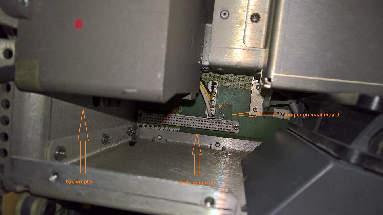
It is not the quad that needs this adaptation, but the EHT board.
Instead of dismantling the whole projector (to be able to reach the jumpers on the maiboard), it is easier to mod the arrival of the DHV (Drain High Voltage) on the EHT module.
On the old style EHT, the DHV arrives at pins 27 and 28. On the new style EHT, the DHV arrives at pins 29 and 30. Someone has posted a picture of the mod in the past here on the forum, i can't find it right now.
Maibe Robin can help with a picture of the modded EHT ?
|
|
| Back to top |
|
|
virusc
Joined: 11 Apr 2007
Posts: 358
Location: Massachusetts
|
|
| Back to top |
|
|
Hulio
Joined: 15 Apr 2006
Posts: 494
Location: Belgium
|
| Posted: Fri Dec 29, 2023 12:20 am Post subject: |
|
|
|
Yes, correct.
|
|
| Back to top |
|
|
alb_qwerti
Joined: 30 Sep 2008
Posts: 54
Location: Italy
|
| Posted: Tue Jan 02, 2024 1:40 pm Post subject: |
|
|
Hi guys,
Sorry for the late answer but very busy these days.
In the first instance Happy New Year to everyboddy!
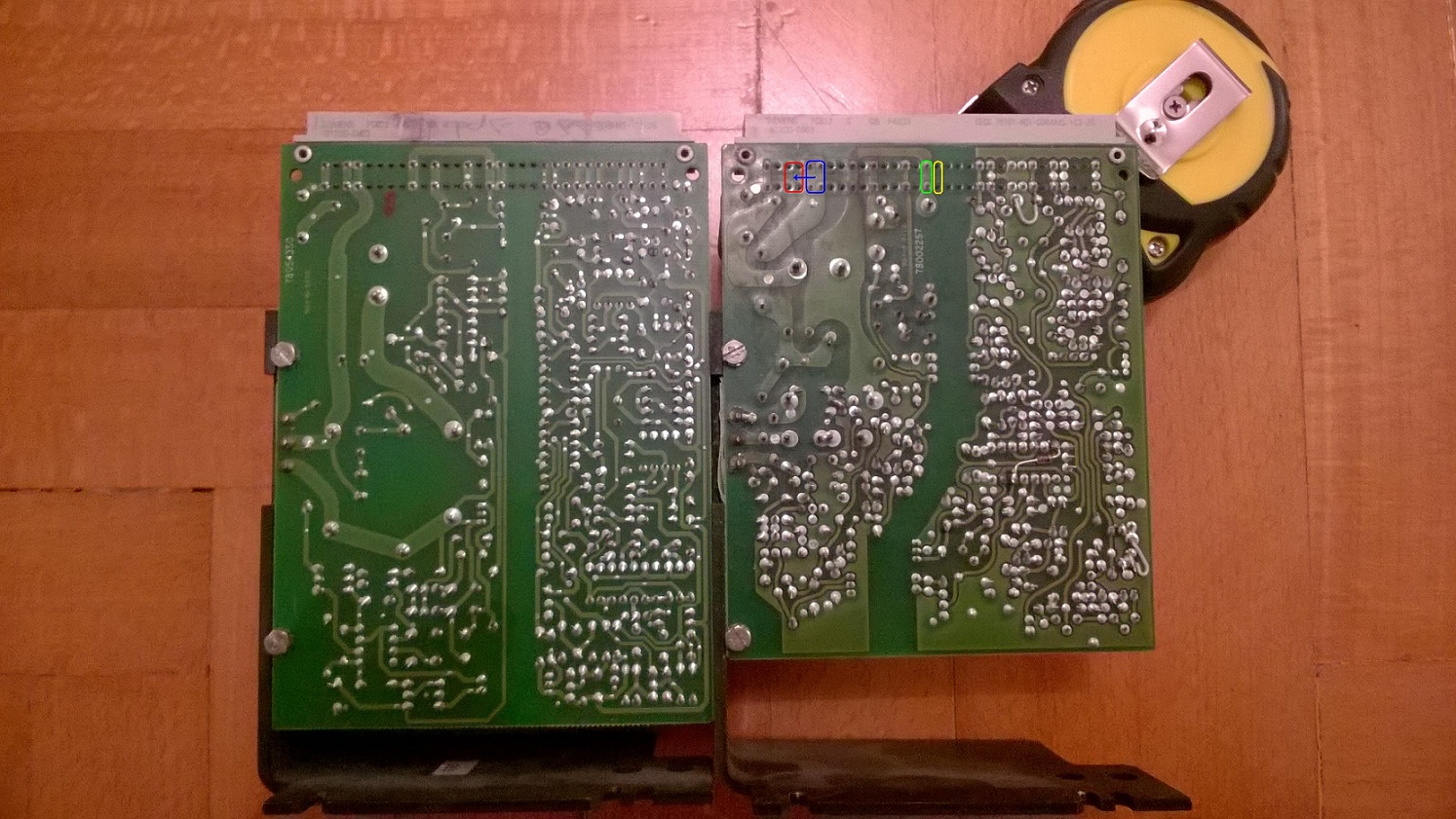
I know that service bulletin. For working an old quadrupler and old EHT on a new frame you should replace the bridge on the main board.
To desolder it you must remove the cover and it's impossible with the PJ hanged on the ceiling.
Otherwise you could jumper the old EHT.
Anyway I was pointing out that with all new parts a very old quadrupler from my BG800 made no oscillations on the 1209/sE.
For years, until the last month.
I thought that it was the same R761743 but maybe it is different.
And finally I'm still not sure that the issue was the quadrupler because the image appeared again only after changing the splitter.
Thanks,
Alberto
| Description: |
|
| Filesize: |
487.78 KB |
| Viewed: |
2372 Time(s) |
|
| Description: |
|
| Filesize: |
307.2 KB |
| Viewed: |
2372 Time(s) |
|
|
|
| Back to top |
|
|
Hulio
Joined: 15 Apr 2006
Posts: 494
Location: Belgium
|
| Posted: Tue Jan 02, 2024 2:42 pm Post subject: |
|
|
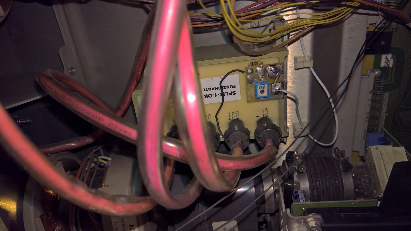
Happy New Year to all.
Yes, a failing splitter will give HV oscillation too, in the form of sudden change in focus and horizontal width.
Glad to hear the three-eyed monster is back in business.
|
|
| Back to top |
|
|
virusc
Joined: 11 Apr 2007
Posts: 358
Location: Massachusetts
|
| Posted: Tue Jan 02, 2024 2:49 pm Post subject: |
|
|
|
Thanks for the pictures. That is helpful. hopefully this stays on the forum for a long time for others.
|
|
| Back to top |
|
|
alb_qwerti
Joined: 30 Sep 2008
Posts: 54
Location: Italy
|
| Posted: Tue Jan 02, 2024 3:32 pm Post subject: |
|
|
Hulio, but do you think that I stepped on a bad splitter again after the last was death?
This one seems like new but the focus and convergence are gone.
More the PJ worm up and more the focus worsen and oscillation become more evident.
Could it be that I havent perfectly soldered the two point of the splitter white wire?
Looking at it seems perfectly soldered anyway.
In this moment I tried the old EHT with the pin bridged.
Still oscillation (even more) and bad focus.
Help !!
|
|
| Back to top |
|
|
Hulio
Joined: 15 Apr 2006
Posts: 494
Location: Belgium
|
| Posted: Tue Jan 02, 2024 4:28 pm Post subject: |
|
|
Yes, very possible to be a bad splitter again. Won't be for the first time, take a look at this post, for instance:
https://www.curtpalme.com/forum_archived/viewtopic.php@t=41457.html
The problem with quads and splitter is that, mostly, you can't see if they are deffective. Even if they look fine on outside, they can arch inside. This is a well known problem due to the potting silicone they used. Newer quads and splitters are even less reliable. Micro-cracks in the potting compound leads to internal arching.
And should that HV-feedback wire on the splitter be faulty soldered, the self protecting circuit would kick in directly, i think.
Anyway, the core of the wire must be soldered on the contact close to the edge of the splitter, while the mesh wire on the contact in the middle.
|
|
| Back to top |
|
|
alb_qwerti
Joined: 30 Sep 2008
Posts: 54
Location: Italy
|
| Posted: Tue Jan 02, 2024 6:21 pm Post subject: |
|
|
Hi Hulio,
I think that a bad solder does not give feedback to EHT too.
Anyway it seems correct, I soldered the same way as the faulty one.
The wire mesh, even if it is not completely covered with tin, is firmly connected.
I had a look at the link of the faulty splitters and I have exactly the same syntoms.
I'll look for another one, even if I bought this one as tested working.
Thanks,
Alberto
| Description: |
|
| Filesize: |
418.13 KB |
| Viewed: |
2348 Time(s) |
|
|
|
| Back to top |
|
|
alb_qwerti
Joined: 30 Sep 2008
Posts: 54
Location: Italy
|
| Posted: Tue Jan 02, 2024 6:38 pm Post subject: |
|
|
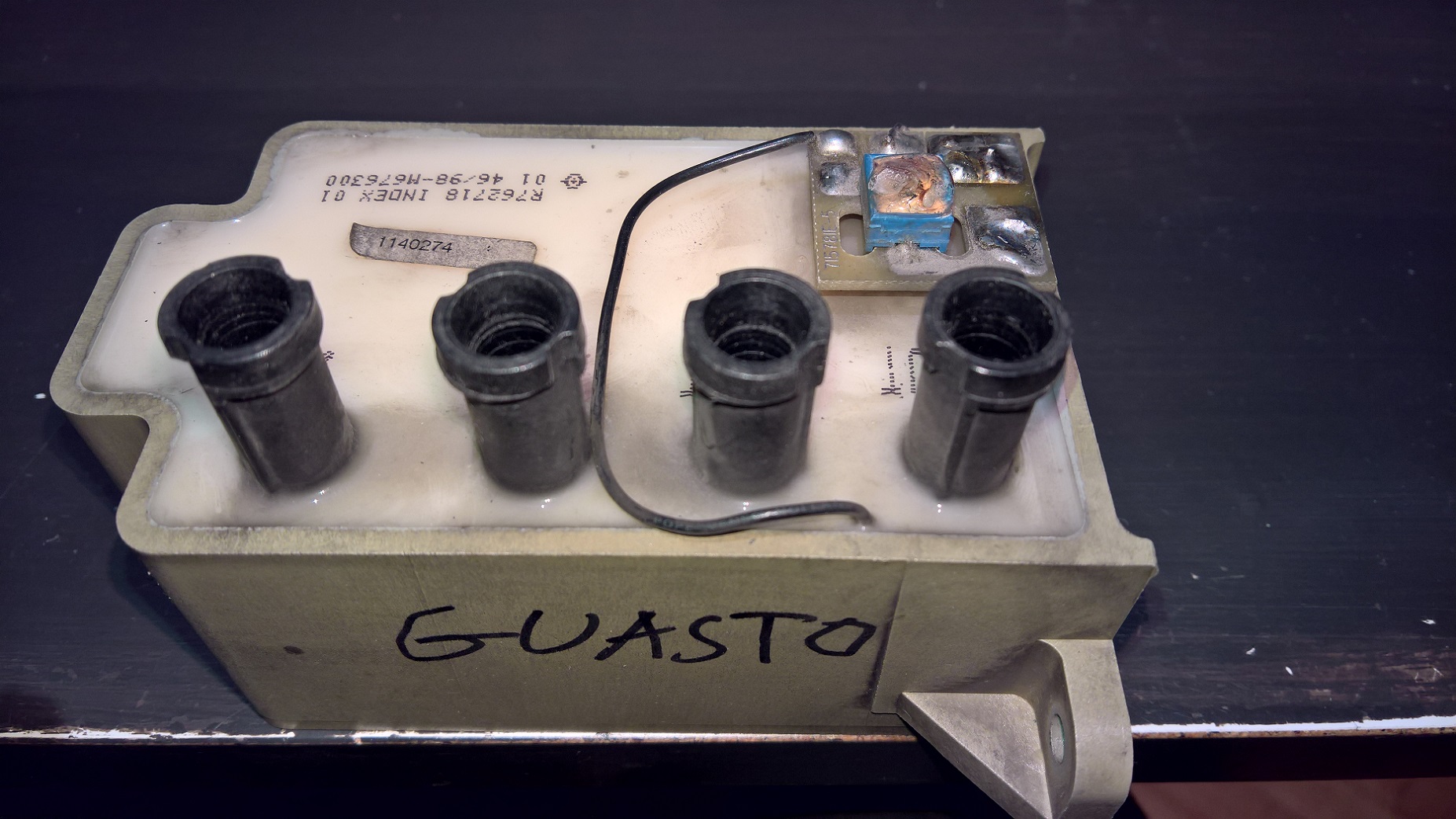
Is it possible that in my old splitter the only issue is that melted part over the circuit that I don't know what is it ?
Thanks for your help.
| Description: |
|
| Filesize: |
489.54 KB |
| Viewed: |
2345 Time(s) |
|
|
|
| Back to top |
|
|
Hulio
Joined: 15 Apr 2006
Posts: 494
Location: Belgium
|
| Posted: Tue Jan 02, 2024 8:30 pm Post subject: |
|
|
Wow, that is roasted. Don't use it anymore, it will take down the EHT board or (and) the quad.
The splitter should receive 33,7KV from the quad. That mini-board on the splitter have a 1MOhm resistor on it, and the blue potentiometer is factory adjusted for a 1/1000 divider. The white coax cable gives feedback to the EHT, reporting the voltage present on the splitter. So if that pot is damaged, the feedback voltage is not accurate anymore.
There are two ways to check the right voltage into into the splitter. Measuring with a precision multimeter onto the soldering point where the core of the white feedback cable is soldered, or using a HV probe connected to one of the three "OUT" connectors on the splitter. Both should read 33,4V (a HV probe has also a 1/1000 divide resistor on it, so the real voltage would be 33,4KV).
Anyway, don't mess with second option if you are not familiar with high voltage work. Just try another splitter.
|
|
| Back to top |
|
|
|
|


