|
As this forum is rarely used anymore, we've locked it. Feel free to browse and read. Questions? Please reach out to us directly. Cheers! |

|
 |
|
|
| Author |
Message |
gjaky
Joined: 05 Jun 2010
Posts: 2802
Location: Budapest, Hungary
|
| Posted: Thu Sep 08, 2016 5:07 pm Post subject: Barco 909 Porn |
|
|
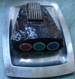
Let the pictures speak...
This one from a fairly old Barco Cine 9 or 909 neckboard:

Interesting that they changed the peaking on the newer hybrids (2x75Ohm vs 2x220 Ohm and 1.2k vs. 330 Ohm), hard core tinkerers might want to try if there is any visible difference...

_________________
projectors in the past : NEC 6-9PG xtra, Electrohome Marquee 6-7500, NEC XG 1351 LC ( with super modified Electrohome VNB neckboard !!!)
current: VDC Marquee 9500LC
The MOD: VNB-DB, VIM-DB
|
|
| Back to top |
|
 |
cmjohnson

Joined: 03 Apr 2006
Posts: 5180
Location: Buried under G90s
|
| Posted: Thu Sep 08, 2016 11:30 pm Post subject: |
|
|
No, don't. Those are ceramic substrates and are not to be messed with unless you have the very specialized tools and knowledge
required simply to remove and replace the resistors. Using ordinary solders will DESTROY the traces.
If you are not FORMALLY TRAINED and QUALIFIED to do component repairs on thick film substrates, you do not know HOW to do it
and your attempt to simply replace two resistors WILL end in DESTRUCTION of the circuit.
I can not stress this strongly enough. DON'T DO IT. YOU WILL FAIL.
Even I don't mess with those. I have Mad Skillz with a soldering iron and a stereo zoom microscope and SMT handling tools, but
I am not thick film qualified and wouldn't touch that job with a 30 foot pole.
|
|
| Back to top |
|
|
Tim in Phoenix

Joined: 21 Oct 2006
Posts: 4409
Location: Phoenix
|
| Posted: Fri Sep 09, 2016 12:28 am Post subject: |
|
|
Yeah
Those look real Sturdy!!!!
|
|
| Back to top |
|
|
cmjohnson
Joined: 03 Apr 2006
Posts: 5180
Location: Buried under G90s
|
| Posted: Fri Sep 09, 2016 12:33 am Post subject: |
|
|
I just did some reading on this and for this to work, APPARENTLY, you need solders that contain Indium which are formulated specifically for thick film soldering jobs. And as I gather it, temperature control is critical and the solder alloy has to be the right one for the chosen thick film substrate and metalization.
In short, don't try this at home, kids.
|
|
| Back to top |
|
|
gjaky
Joined: 05 Jun 2010
Posts: 2802
Location: Budapest, Hungary
|
| Posted: Fri Sep 09, 2016 5:23 am Post subject: |
|
|
Of course I was not serious about modding the boards, but hoarders might look up their parts stash and find if they have different hybrids on the boards and then try those boards...
BTW I have seen some hybrid circuits already and I have the feeling this one is a quite low budget. No thick film resistors at all. And Ive never seen bond wires this long for connecting to transistors. long thin wires and traces mean stray inductances, those are unwelcome with high frequency circuits.
_________________
projectors in the past : NEC 6-9PG xtra, Electrohome Marquee 6-7500, NEC XG 1351 LC ( with super modified Electrohome VNB neckboard !!!)
current: VDC Marquee 9500LC
The MOD: VNB-DB, VIM-DB
|
|
| Back to top |
|
|
Curt Palme
CRT Tech
Joined: 08 Mar 2006
Posts: 24396
Location: Langley, BC
TV/Projector: All of them!
|
| Posted: Fri Sep 09, 2016 2:21 pm Post subject: |
|
|
|
I've had lots of failures of these custom BArco chips. Usually there's simply no video output, although I've had ones come on full brightness, and one with retrace lines. There's no repairing these AFAIK.
|
|
| Back to top |
|
|
gjaky
Joined: 05 Jun 2010
Posts: 2802
Location: Budapest, Hungary
|
| Posted: Fri Sep 09, 2016 4:29 pm Post subject: |
|
|
More porn!
I drawed back the circuit diagram of this hybrid.

On the right there is the schematic of a Sanyo VPA hybrid which is essentially same as a Marquee neckboard design as well, it is recognized in engineering handbooks as cascode stage with output buffer, this is the pretty much standard circuit for CRT amplifier.
On the left side there is the Barco hybrid's schematic diagram. If you look at them from far they appear quite similar, but at second glance there is a differences.
-The power resistors are tied to Q1's collector instead of it's base (or close to it).
Here are some close ups from the transistors:
Q1:

Q2, please note the grey parts circled, those parts are probably burnt out already, high frequency power transistors are often constructed of several "smaller" transistors tied in parallel, with an internal fuse, a part of these small transistors might burn out in an event of failure, still the overal transistor might remain functional, and this may be the case here as well, since this transistor still measures good from the outside.

Q3, was somewhat damaged when I ripped-off the RF shielding, still the transistor is functional.

Q4:

_________________
projectors in the past : NEC 6-9PG xtra, Electrohome Marquee 6-7500, NEC XG 1351 LC ( with super modified Electrohome VNB neckboard !!!)
current: VDC Marquee 9500LC
The MOD: VNB-DB, VIM-DB
|
|
| Back to top |
|
|
gjaky
Joined: 05 Jun 2010
Posts: 2802
Location: Budapest, Hungary
|
| Posted: Sat Sep 10, 2016 3:26 pm Post subject: |
|
|
Also what is worth mentioning in the current barco design is that they paralleled Q3 and Q4 probably to fit in the transistors dissipation limit, but both transistor have to stand the whole voltage (and in this circuit Q3 and Q4 is under the most stress both in dissipation and in voltage) once they took the pain to use two transistors for that stage they would have been better to went with a so-called sliding cascode circuit, where two lower voltage transistor could be connected in series and adding the two base resistors would ensure equal voltage division between the two transistors. And as you know with lower voltage transistors it is easier to find faster.

_________________
projectors in the past : NEC 6-9PG xtra, Electrohome Marquee 6-7500, NEC XG 1351 LC ( with super modified Electrohome VNB neckboard !!!)
current: VDC Marquee 9500LC
The MOD: VNB-DB, VIM-DB
|
|
| Back to top |
|
|
gjaky
Joined: 05 Jun 2010
Posts: 2802
Location: Budapest, Hungary
|
| Posted: Mon Sep 12, 2016 7:04 pm Post subject: |
|
|
Some more shots, this time off a Sanyo VPA13.
Interesting is that Q1-Q3 transistors look structurally different from the ones used in the Barco, probably because this is the "FBET" process they mentioned in every datasheet.
Q1-Q3:

Q4, low voltage transistor looks similar to the barco transistors

The diodes are also in bare form in the VPA:

_________________
projectors in the past : NEC 6-9PG xtra, Electrohome Marquee 6-7500, NEC XG 1351 LC ( with super modified Electrohome VNB neckboard !!!)
current: VDC Marquee 9500LC
The MOD: VNB-DB, VIM-DB
|
|
| Back to top |
|
|
gjaky
Joined: 05 Jun 2010
Posts: 2802
Location: Budapest, Hungary
|
| Posted: Mon Oct 10, 2016 6:02 pm Post subject: |
|
|
This time I caught an MRF548 (with broken emitter lead), thought I have nothing to loose if I disassemble, and in the end I even managed to repair it...
It is interesting that it is actually two transistor dies in one package (tied parallel).


_________________
projectors in the past : NEC 6-9PG xtra, Electrohome Marquee 6-7500, NEC XG 1351 LC ( with super modified Electrohome VNB neckboard !!!)
current: VDC Marquee 9500LC
The MOD: VNB-DB, VIM-DB
|
|
| Back to top |
|
|
|
|
|
|
|
You cannot post new topics in this forum
You cannot reply to topics in this forum
You cannot edit your posts in this forum
You cannot delete your posts in this forum
You cannot vote in polls in this forum
You cannot attach files in this forum
You can download files in this forum
|
Forum powered by phpBB © phpBB Group
|
|


