| Author |
Message |
gnnash
Joined: 10 Jul 2013
Posts: 216
Location: Lake Elmo, MN
|
| Posted: Wed Jul 02, 2014 1:10 pm Post subject: Neck Board Mod for LCP09 in 1209s? |
|
|
Finally got to refill my new green tube with glycol last night, no leaks as of this morning, after work I intend to put the tube back in and setup the projector.
However, I understand that I will need to do a mod to my neck board. Old tube was an LPB03, new tube is an LCP09.
Is it just as simple as putting a jumper between pins 2 and 6? Also, pins 1 and 2 are under a plastic cover, not extending out the back of the PCB. Will I have any noise issues with a long jumper from the back to the front of the neck card?
I found the following pinouts which suggest to me that a jumper between 2 and 6 would give me the missing G2 I need at pin 2:

|
|
| Back to top |
|
 |
Curt Palme
CRT Tech
Joined: 08 Mar 2006
Posts: 24396
Location: Langley, BC
TV/Projector: All of them!
|
| Posted: Wed Jul 02, 2014 1:37 pm Post subject: |
|
|
|
Yes, jumper pin 2 to 6, that should do it.
|
|
| Back to top |
|
|
barclay66

Joined: 27 Jun 2011
Posts: 1304
Location: Germany
TV/Projector: Marquee 9500 Ultra
|
| Posted: Wed Jul 02, 2014 1:37 pm Post subject: |
|
|
Hi,
You are correct. I don't think that there will be any noise issue with the jumper wire. On the Marquee the G2 connection is always done with a single wire and a connector that goes straight to the tube's G2 input pin...
Regards,
barclay66
| Description: |
|
| Filesize: |
30.18 KB |
| Viewed: |
2442 Time(s) |
|
|
|
| Back to top |
|
|
gnnash
Joined: 10 Jul 2013
Posts: 216
Location: Lake Elmo, MN
|
| Posted: Wed Jul 02, 2014 3:05 pm Post subject: |
|
|
Thanks for the confirmation!
Unfortunately, my neck boards do not have pins 1 and 2 exposed on the rear of the PCB, they are hidden under a cover on the socket itself, on the front side of the PCB. Kinda hard to explain without a picture...
|
|
| Back to top |
|
|
Decibel

Joined: 31 May 2007
Posts: 904
Location: Roma - Italia
|
| Posted: Fri Jul 04, 2014 9:31 am Post subject: |
|
|
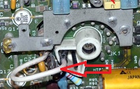
| gnnash wrote: | | Unfortunately, my neck boards do not have pins 1 and 2 exposed on the rear of the PCB, they are hidden under a cover on the socket itself, on the front side of the PCB. |
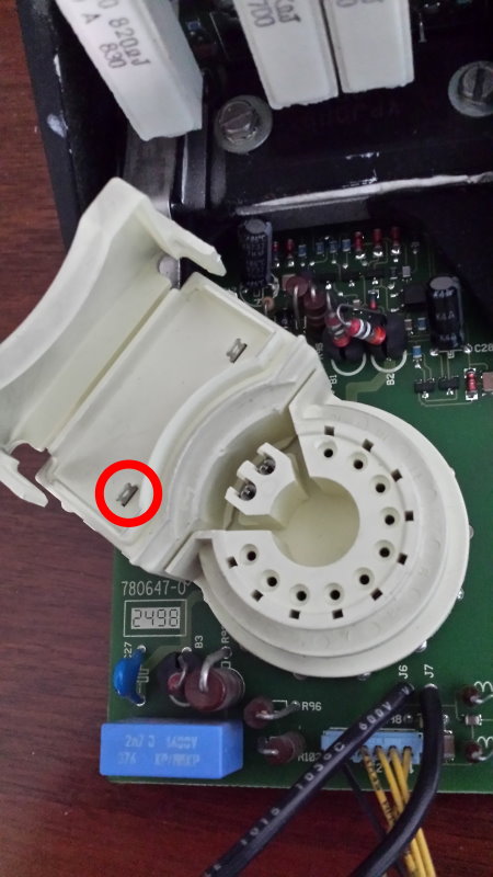
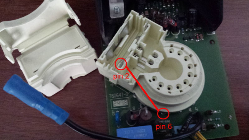
You can remove (or make a little hole) in the cover of the socket, see the pictures below.
There's an extra pin 2 where you can solder a wire.
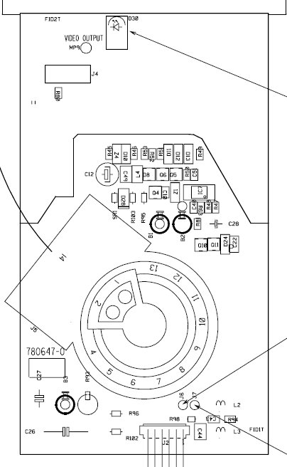
| Description: |
| Pinout of R762839 neckboard |
|
| Filesize: |
53.69 KB |
| Viewed: |
2374 Time(s) |
|
| Description: |
| Open the cover of the socket |
|
| Filesize: |
70.27 KB |
| Viewed: |
2374 Time(s) |
|
| Description: |
|
| Filesize: |
54.98 KB |
| Viewed: |
2374 Time(s) |
|
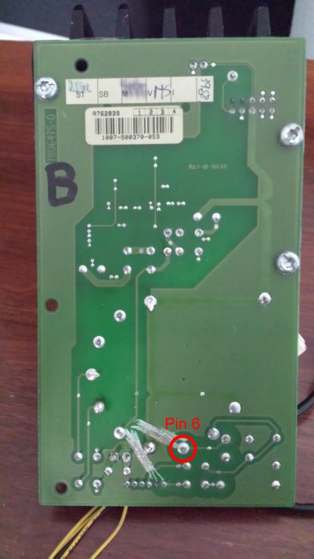
| Description: |
| Remove cover of the socket |
|
| Filesize: |
74.65 KB |
| Viewed: |
2374 Time(s) |
|
_________________
Domenico (Barco fan!)
|
|
| Back to top |
|
|
gnnash
Joined: 10 Jul 2013
Posts: 216
Location: Lake Elmo, MN
|
| Posted: Mon Jul 07, 2014 12:53 pm Post subject: |
|
|
Right, that's exactly where I tapped into pin 2, it's the only location to do so.
There are already holes at the back (by the hinged part) of the cover to run a jumper wire out when you close it back up.
|
|
| Back to top |
|
|
|
|


