| Author |
Message |
Zerog
Joined: 05 Jan 2013
Posts: 35
Location: Southern California
|
| Posted: Mon Jan 07, 2013 1:02 am Post subject: Another Marantz SR 7002 Issue |
|
|
First post here - I'm happy to find this site!
I have a Marantz SR7002, out of warranty, with a display issue - The display variable output for input, volume, etc. looks corrupted. The selector switch affects it to make it flash on and off briefly. Display stays on briefly, but cannot cycle through inputs, etc. If I touch the knob again it goes blank.
I've done the factory reset. Heard relay clicking from the unit. Did this several times with no success.
Amp section seems to work OK, as the front two channels respond to an external stereo preamp.
Could the issue be in the selector switch? Bad solder? Blown IC?
I'd appreciate any advice about troubleshooting this unit. Anyone have a schematic to share?
Thanks for any guidance!
|
|
| Back to top |
|
 |
macgyver655
Joined: 22 Aug 2007
Posts: 8508
|
| Posted: Mon Jan 07, 2013 5:06 pm Post subject: |
|
|
Well Zerog, I usually only help regular members on here. It's not a repair all site. But you can try doing a reset and see if it helps. With receiver in standby, press and hold the "Multi and Speakers A/B" buttons for at least 5 seconds until the unit turns on. That should set everything to factory default.
Of course if you were to become a club member I could help you with diagnostics...... 
|
|
| Back to top |
|
|
Zerog
Joined: 05 Jan 2013
Posts: 35
Location: Southern California
|
| Posted: Mon Jan 07, 2013 5:30 pm Post subject: |
|
|
Hi, Thanks for the reply - I didn't realize this was a membership forum - it came up through a search.
Previously tried the factory reset, but with the power on. It appears to go through a cycle that sounds like relays clicking. No clicking with the reset you mentioned.
I'm not a tech, but I do have a DMM, can solder, and have done small repairs and upgrades before (recapping old receivers, crossovers, etc).
My concern is that the microprocessor is cooked and this won't ever work again without replacing major boards at considerable expense.
Do you have an idea what's wrong? Could you provide the assist necessary to repair this? That would be worth joining, IMHO
Thanks!
|
|
| Back to top |
|
|
macgyver655
Joined: 22 Aug 2007
Posts: 8508
|
| Posted: Mon Jan 07, 2013 6:05 pm Post subject: |
|
|
Well technically it's not a members site but member fees help to pay to keep the site going. Of course this may sound hypocritical coming from me since I'm not a paid member but my contribution to the site is helping those requiring it. If there was a membership for technical help I think I would pass, LOL. And I'm sure if you have read some of the other threads that I have assisted in I'm sure you would agree that I put in a lot of effort.
I'm merely trying to help produce some revenue to help keep the site going with my technical assistance.
So I'll tell you what. If I give you some assistance and we can get you up and running would you then consider a donation to the site?
|
|
| Back to top |
|
|
macgyver655
Joined: 22 Aug 2007
Posts: 8508
|
| Posted: Mon Jan 07, 2013 6:07 pm Post subject: |
|
|
| macgyver655 wrote: | Well technically it's not a members site but member fees help to pay to keep the site going. Of course this may sound hypocritical coming from me since I'm not a paid member but my contribution to the site is helping those requiring it. If there was a membership for technical help I think I would pass, LOL. And I'm sure if you have read some of the other threads that I have assisted in I'm sure you would agree that I put in a lot of effort.
I'm merely trying to help produce some revenue to help keep the site going with my technical assistance.
So I'll tell you what. If I give you some assistance and we can get you up and running would you then consider a donation to the site? |
Hey, what the hell is up with my post? Why are there links in some of the words I posted?
Edit: now they are gone. Never saw that before......
|
|
| Back to top |
|
|
Zerog
Joined: 05 Jan 2013
Posts: 35
Location: Southern California
|
| Posted: Mon Jan 07, 2013 6:08 pm Post subject: |
|
|
Sounds eminently fair to me. Thanks for the offer.
Where do we start?
|
|
| Back to top |
|
|
macgyver655
Joined: 22 Aug 2007
Posts: 8508
|
| Posted: Mon Jan 07, 2013 6:17 pm Post subject: |
|
|
Alright, I recently had an AVR with a scrambled display which I also fist thought the worse but it ended up just being a shorted voltage line in a complete different location. So the first place to start is to test the supply voltages coming out of the regulator board. I have attached a picture. I'm in a hurry so just did a quick screenshot so disregard my desktop image, lol. Do your best to test all those output voltages and let me know what you have or don't have. I have to run out for a few hours so I'll check in when i get back.
| Description: |
|

Download |
| Filename: |
SR7002.jpg |
| Filesize: |
482.17 KB |
| Downloaded: |
853 Time(s) |
|
|
| Back to top |
|
|
Zerog
Joined: 05 Jan 2013
Posts: 35
Location: Southern California
|
| Posted: Mon Jan 07, 2013 10:15 pm Post subject: |
|
|
Measured as best I could, though didn't always pay attention to + or- voltages. Surprised to see so many variances. FWIW, the amp section seems to work on at least 4 of the channels (FR, FL, RR, RL) with an external preamp attached.
Here's the results:
Marantz SR7002 Regulator Board
CN93 OK
CN92 - not checked
BN92 Pin1=20.7V , s/b +18V
Pin2=21.2V, s/b-18V
Pin8=4.7, s/b 0V
BN91 Pin7=0V, s/b +12
CN95 Pin4=4.8V, s/b 0V
Pin5=4.8V, s/b 0V
BN94 Pins 4, 5= 0.82Veach, s/b +5V
CN96 Pin3=0V, s/b+12
BN97 1,2 OK
Thanks again!
|
|
| Back to top |
|
|
macgyver655
Joined: 22 Aug 2007
Posts: 8508
|
| Posted: Mon Jan 07, 2013 10:36 pm Post subject: |
|
|
There are some pin numbers in your post that make no sense and some missing. I made a chart for you to just fill in the blanks. Make sure you check whether it's + or -. I need specifics.
CN93:
Pin 1:_____
Pin 3:_____
Pin 4:_____
Pin 5:_____
Pin 8:_____
BN92:
Pin 1:_____
Pin 2:_____
Pin 4:_____
Pin 5:_____
BN91:
Pin 5:_____
Pin 7:_____
CN95:
Pin 1:_____
Pin 3:_____
BN94:
Pin 1:_____
Pin 3:_____
Pin 4:_____
Pin 5:_____
Pin 8:_____
CN96:
Pin 1:_____
Pin 3:_____
BN97-1:
Pin 1:_____
Pin 3:_____
BN97-2
Pin 1:_____
Pin 3:_____
|
|
| Back to top |
|
|
Zerog
Joined: 05 Jan 2013
Posts: 35
Location: Southern California
|
| Posted: Mon Jan 07, 2013 10:49 pm Post subject: |
|
|
|
Roger that - will repeat. The silk-screened board designations are very hard to read - would you happen to have a board diagram handy?
|
|
| Back to top |
|
|
Zerog
Joined: 05 Jan 2013
Posts: 35
Location: Southern California
|
| Posted: Mon Jan 07, 2013 11:19 pm Post subject: |
|
|
Here they are:
CN93:
Pin 1: -15.36
Pin 3: +15.16
Pin 4: +4.99
Pin 5: +4.99
Pin 8: +4.94
BN92:
Pin 1: +20.8
Pin 2: -21.4
Pin 4: +15.1
Pin 5: +4.9
BN91:
Pin 5: +4.9
Pin 7: 0.0
CN95:
Pin 1: -15.36
Pin 3: -15.17
BN94:
Pin 1: -15.36
Pin 3: +15.18
Pin 4: +0.81
Pin 5: +0.81
Pin 8: +4.94
CN96:
Pin 1: +8.8
Pin 3: 0.0
BN97-1:
Pin 1: -15.35
Pin 3: +15.6
BN97-2
Pin 1: -15.35
Pin 3: +15.16
|
|
| Back to top |
|
|
macgyver655
Joined: 22 Aug 2007
Posts: 8508
|
| Posted: Mon Jan 07, 2013 11:39 pm Post subject: |
|
|
|
On that regulator board there are 2 fuses, F901 and F902. See if they are blown.
|
|
| Back to top |
|
|
Zerog
Joined: 05 Jan 2013
Posts: 35
Location: Southern California
|
| Posted: Tue Jan 08, 2013 12:20 am Post subject: |
|
|
| macgyver655 wrote: | | On that regulator board there are 2 fuses, F901 and F902. See if they are blown. |
Thanks for the fast response. Obviously they're not glass fuses. Very difficult to see without a teardown. Would you happen to have a board diagram? That would help tremendously.
|
|
| Back to top |
|
|
Zerog
Joined: 05 Jan 2013
Posts: 35
Location: Southern California
|
| Posted: Tue Jan 08, 2013 1:00 am Post subject: |
|
|
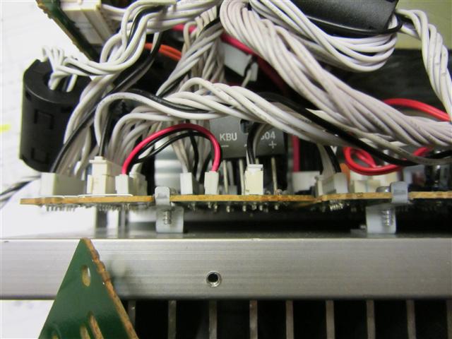
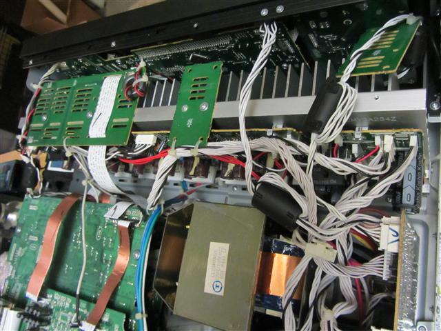
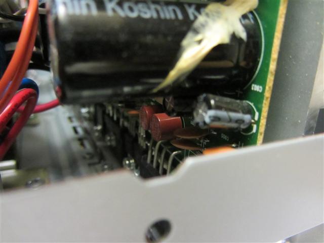
I see two small brown cylindrical shapes that say 5A 250V, so could be the fuses you mentioned. They appear to be soldered in. I was looking for a fusible resistor, too.
The board is attached with one screw but there are several transistors and/or regulators that attach it to the heat sink. Can this be tipped back just a little without cracking the trans/regs?
| Description: |
|
| Filesize: |
58.1 KB |
| Viewed: |
19118 Time(s) |
|
| Description: |
|
| Filesize: |
76.7 KB |
| Viewed: |
19118 Time(s) |
|
| Description: |
|
| Filesize: |
38.5 KB |
| Viewed: |
19118 Time(s) |
|
|
|
| Back to top |
|
|
macgyver655
Joined: 22 Aug 2007
Posts: 8508
|
| Posted: Tue Jan 08, 2013 1:00 am Post subject: |
|
|

|
|
| Back to top |
|
|
macgyver655
Joined: 22 Aug 2007
Posts: 8508
|
| Posted: Tue Jan 08, 2013 1:04 am Post subject: |
|
|
|
Ha, AVR's are almost never easy to work on. You just have to suck it up and remove what needs to be removed.
|
|
| Back to top |
|
|
Zerog
Joined: 05 Jan 2013
Posts: 35
Location: Southern California
|
| Posted: Tue Jan 08, 2013 1:59 am Post subject: |
|
|
| macgyver655 wrote: | | Ha, AVR's are almost never easy to work on. You just have to suck it up and remove what needs to be removed. |
Yep, that's them. I'm gonna see if I can just measure them without a major teardown. This is the appropriate time to wonder why they just didn't put an access plate on the bottom of the unit.
|
|
| Back to top |
|
|
Zerog
Joined: 05 Jan 2013
Posts: 35
Location: Southern California
|
| Posted: Tue Jan 08, 2013 3:20 am Post subject: |
|
|
OK...a medium teardown. Sure hope I get it all back together - those flat ribbon connectors that just push in can be challenging.
BTW...the fuses are good. I didn't unsolder them, but there's continuity across each one.
What's next?
|
|
| Back to top |
|
|
macgyver655
Joined: 22 Aug 2007
Posts: 8508
|
| Posted: Tue Jan 08, 2013 3:53 pm Post subject: |
|
|
|
I just noticed that ic91 is optional for the 7002. Does yours have ic91?
|
|
| Back to top |
|
|
macgyver655
Joined: 22 Aug 2007
Posts: 8508
|
| Posted: Tue Jan 08, 2013 4:16 pm Post subject: |
|
|
If no ic91 then lets continue. You have to make some tests at connector CN62 on the Power PWB. Note that you have to test across pins 1 and 2 with DMM set on A/C. Pins 3,6 and 7 are D/C with chassis as gnd.
CN62:
Pins 1 and 2:_____ A/C
Pin 3:_____
Pin 6:_____
Pin 7:_____

|
|
| Back to top |
|
|
|
|


