| Author |
Message |
CasetheCorvetteman

Joined: 09 Nov 2008
Posts: 6326
Location: Australia
|
| Posted: Thu Feb 12, 2009 2:17 pm Post subject: Arcing issues |
|
|
Gday people, ive got a Sony VPH-1001QM with some pretty serious arcing problems.
Today i replaced the HV leads with some good ones, its still arcing from the blue HV lead to the chassis about 1 or 2 mm from the anode cap, i would have to think this is what is causing the spark to jump from a chassis screw that holds down one of the transformers to the same transformer on the board with Pc in the corner (its got two of these black transformers, 1 red lead each going to the HV block where the 3 HV leads from the tubes connect).
The HV lead from the red tube is arcing to the blue deflector yoke about 5 mm from where it enters the HV block.
The HV lead from one of the transformers is arcing to the green deflector yoke about 3 mm from where it enters the HV block.
The green HV lead seems to be cured of all arcing.
Is there more to this issue than possible buggered leads? Id have thought the flow of electrons would always take the easiest path, which i wouldnt expect to be through the HV lead jackets unless there is no where for it to go at the HV block. (its an orange looking thing with 5 connection points on it incase im calling it the wrong thing)
I know alot of people will think "this bloke is mad for bothering with a dirty old Sony 1001", but its abit more than that to me, and its also a sense of achievement to restore something (if you could call it restoring) that to me does the job i need it to do very well.
I have been in contact with Curt about this and his help has been exceptional as always, but Curt is a busy man and i dont really want to take up his time with this any more than i have to, im starting to feel bad emailing him once a day with such a problem.
Does anyone have any suggestions on what else i could look for on this issue? Thanks in advance to anyone that tries to help 
|
|
| Back to top |
|
 |
Curt Palme
CRT Tech
Joined: 08 Mar 2006
Posts: 24396
Location: Langley, BC
TV/Projector: All of them!
|
| Posted: Thu Feb 12, 2009 3:40 pm Post subject: |
|
|
THis is a bit of a strange one. I sent Case replacement tubes that worked fine in a set here. He took off the HV leads (ECP style, wrong HV lead end) and put his original Sony ones onto my tubes. THey arced, although these were off his original tubes that didn't arc.
If I remember correctly, he then put my original leads back on, and transferred the HV lead ends from his Sony leads onto my E'home leads. Still gets arcing.
I don't think I've ever had arcing in the Sony 10XX series of sets, and I've seen some pretty nasty looking nicotine covered leads come out of those 10XX sets.
Anyone in the QLD area with an HV probe? All I can think is that somehow during tube changing, the Hv transformer is putting out more than the standard HV voltage, and that's what's causing the arcing.
????
|
|
| Back to top |
|
|
CasetheCorvetteman
Joined: 09 Nov 2008
Posts: 6326
Location: Australia
|
| Posted: Thu Feb 12, 2009 3:43 pm Post subject: |
|
|
|
All that is spot on Curt, pretty much a shortened version of my week!! Cheers mate
|
|
| Back to top |
|
|
outwest
Joined: 17 Dec 2006
Posts: 212
Location: Honolulu
|
| Posted: Thu Feb 12, 2009 6:12 pm Post subject: |
|
|
Your problem has a familiar sound to it. I had a 37" CRT monitor that had serious arcing as soon as it was powered on. I asked a place that did monitor repairs and another general TV repair shop what the problem might be. This was a very large and heavy unit, so bringing it in to the shop was a real problem. I made it clear to them that I would pay for the consultation or would pay for a sevice call. Neither place was reaally interested in helping. The only suggestion that I got is to use more insulation. Well, when I tried that, the arc didn't just go the short distance to the "safety bridge" it arced at least 4 inches across to one of the PCB's.
After some internet reading, I took a chance on getting another flyback transformer and that fixed the arcing problem. I guess that some internal arcing in the flyback had damaged some of the windings and it was putting out a much higher voltage than spec.
|
|
| Back to top |
|
|
AnalogRocks
Forum Moderator
Joined: 08 Mar 2006
Posts: 26706
Location: Toronto, Ontario, Canada
TV/Projector: Sony 1252Q, AMPRO 4000G
|
| Posted: Thu Feb 12, 2009 6:13 pm Post subject: |
|
|
If all else fails you could pull the flyback out and make yer own stun gun. 
I know not helpfull at all.
_________________
Tech support for nothing
CRT.
HD done right!
|
|
| Back to top |
|
|
outwest
Joined: 17 Dec 2006
Posts: 212
Location: Honolulu
|
| Posted: Thu Feb 12, 2009 6:24 pm Post subject: |
|
|
I was stunned to see that arc. I was more stunned to see what it did to the PCB that was "ground zero". 
It is appropriate that the emoticon is labeled "shock".
|
|
| Back to top |
|
|
CasetheCorvetteman
Joined: 09 Nov 2008
Posts: 6326
Location: Australia
|
| Posted: Fri Feb 13, 2009 2:54 am Post subject: |
|
|
| outwest wrote: | Your problem has a familiar sound to it. I had a 37" CRT monitor that had serious arcing as soon as it was powered on. I asked a place that did monitor repairs and another general TV repair shop what the problem might be. This was a very large and heavy unit, so bringing it in to the shop was a real problem. I made it clear to them that I would pay for the consultation or would pay for a sevice call. Neither place was reaally interested in helping. The only suggestion that I got is to use more insulation. Well, when I tried that, the arc didn't just go the short distance to the "safety bridge" it arced at least 4 inches across to one of the PCB's.
After some internet reading, I took a chance on getting another flyback transformer and that fixed the arcing problem. I guess that some internal arcing in the flyback had damaged some of the windings and it was putting out a much higher voltage than spec. |
Sounds like it could be the issue here mate, this arcing will stop at nothing. Itll go through anything in its path.
I have a couple pics here, ive labled this pic where it arced to that screw:


Is it those 2 black items with the 4 red leads coming out of that youre calling a flyback transformer?
| AnalogRocks wrote: | If all else fails you could pull the flyback out and make yer own stun gun.
I know not helpfull at all. |

Its not helpful at all mate no, but it is quite funny none the less 
|
|
| Back to top |
|
|
outwest
Joined: 17 Dec 2006
Posts: 212
Location: Honolulu
|
| Posted: Fri Feb 13, 2009 6:48 am Post subject: |
|
|
Yes, in a TV or CRT monitor the transformer that supplies the high voltage to the anode lead that goes to the socket on the side of the bell of the picture tube is called the flyback transformer. I don't know for sure, but I assumed the name came from the electron beam "flying back" to start another scan.
I wonder if the tubes that you put into the PJ need a different high voltage value to function. I get suspicious of a part "failing" when other components are changed. Would it be worth hooking up the original tubes to see if the problem goes away? It might let you determine if the high voltage transformer is really bad or it is simply not compatible with the different tubes.
I just read the above. It sounds like I know what I am talking about. I don't! 
|
|
| Back to top |
|
|
CasetheCorvetteman
Joined: 09 Nov 2008
Posts: 6326
Location: Australia
|
| Posted: Fri Feb 13, 2009 7:05 am Post subject: |
|
|
Haha!! Thats ok mate, it put another idea on the table for us.
I dont think the tubes would require anything different, they are 07MS Sony tubes, and that is what came out, the numbers on them match the ones that came out, apart from the build dates. Even if i turn the screen pots right down, it still wants to arc, so im not sure what that tells us all.
Would be a far bit of work to get the other tubes back in now, they have no leads on them, but i dont think that would show anything different if i did. If the tubes were not the same type i could see it being worth a shot, but they are the same part number.
|
|
| Back to top |
|
|
CasetheCorvetteman
Joined: 09 Nov 2008
Posts: 6326
Location: Australia
|
| Posted: Fri Feb 13, 2009 10:34 am Post subject: |
|
|
Ok ive got the board out for a look at it, and taken some readings, ive drawn lines on the picture to show where i took the readings:

White line is terminals 4 and 5 on the transformers: 0.48 to 0.5 ohms
Light blue line is a blue thing with PM 155J 400v on the side: 194 ohms
Red line is the other blue thing with PMH203H 1600VHO j on the side: 193 ohms
Brown line is the other 2 small transformers there: 0.39 to 0.41 ohms
C to B on the transistor at the bottom is 407 to 408 ohms
E to B on the same transistor is 436 ohms
C to E on same transistor is 370 ohms
None of the other terminals on the black transformers connected to each other, all seem to be open loop (unless connected obviously by tracks you can see)
Ive got a couple pics from the top to show the rest of it:


|
|
| Back to top |
|
|
outwest
Joined: 17 Dec 2006
Posts: 212
Location: Honolulu
|
| Posted: Sat Feb 14, 2009 8:01 am Post subject: |
|
|
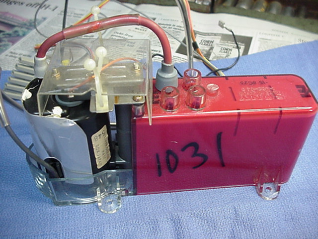
Oh, I see! I am sorry that I didn't read your other thread carefully. The Sony 10XX PJ's that I have seen had SD187, or even SD130, tubes. I made the wrong assumption that you were changing from SD187 to 07MSP. I looked at a few items that I had in a box from a couple of 10XX units that I parted out, (1030 and 1031) The high voltage transformers are different than the one in your pictures. I have attached a photo, just for reference. I looked inside my 1042 and was surprised to see that it does look like the setup that you have. Unfortunately, I don't have any spare parts for this PJ. I looked at the routing of all the high voltage leads and it struck me as being a bit complicated and not entirely obvious. I am not intending to be a smart a$$ here, but it seems like it would be pretty easy to get some of the leads plugged into the wrong sockets. It is just the sort of thing that I am capable of. It is the kind of error that would account for having new problems for no apparent reason.
If you can't come up with a fix, I could take my unit out and we could compare meter readings.
| Description: |
|
| Filesize: |
85.92 KB |
| Viewed: |
11028 Time(s) |
|
|
|
| Back to top |
|
|
CasetheCorvetteman
Joined: 09 Nov 2008
Posts: 6326
Location: Australia
|
| Posted: Sat Feb 14, 2009 6:11 pm Post subject: |
|
|
Thanks heaps for that mate!! Thats great!! I appreciate the effort youve gone to there.
One thing i would like to know (i dont want to put you to the trouble of pulling a projector apart!!) Can you tell me which HV leads connect to what on the splitter on your 1042? Mine from left to right (viewed from the rear) on the 1001 is:
1: red HV
2: green HV
3: left FB transformer
4: blue HV
5: right FB transformer
Is that the same as your 1042?
Thanks again for taking the time mate
|
|
| Back to top |
|
|
outwest
Joined: 17 Dec 2006
Posts: 212
Location: Honolulu
|
| Posted: Sat Feb 14, 2009 6:36 pm Post subject: |
|
|
|
Sure. I will try a clear verbal description or make a quick and dirty illustration of the lead routing. It looks like I will not get to do this until tomorrow night when I get home.
|
|
| Back to top |
|
|
CasetheCorvetteman
Joined: 09 Nov 2008
Posts: 6326
Location: Australia
|
| Posted: Sun Feb 15, 2009 1:56 am Post subject: |
|
|
Thats no worries mate, no rush at all Thanks 
|
|
| Back to top |
|
|
outwest
Joined: 17 Dec 2006
Posts: 212
Location: Honolulu
|
| Posted: Sun Feb 15, 2009 6:53 am Post subject: |
|
|
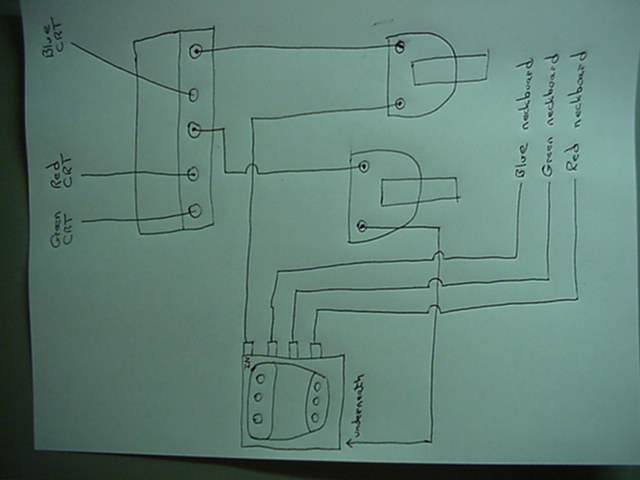
The economic situation has taken a toll here. I went to a car auction today and it was a total bust. Very few cars and almost nothing interesting. My friend and I left early, had something to eat, and I went back to work. The good news is that I got home early and was able to make the attached diagram for the HV section of my 1042. I do hope that it is of some value.
| Description: |
|
| Filesize: |
45.56 KB |
| Viewed: |
10979 Time(s) |
|
|
|
| Back to top |
|
|
CasetheCorvetteman
Joined: 09 Nov 2008
Posts: 6326
Location: Australia
|
| Posted: Sun Feb 15, 2009 9:19 am Post subject: |
|
|
Thanks mate The only difference i can see there is the red and green on mine were back to front compared with your diagram, although im sure that is where i took them from.
Hard to say if that would make a difference, im not sure the exact function of that orange block they all connect to.
|
|
| Back to top |
|
|
Curt Palme
CRT Tech
Joined: 08 Mar 2006
Posts: 24396
Location: Langley, BC
TV/Projector: All of them!
|
| Posted: Fri Feb 20, 2009 3:44 pm Post subject: |
|
|
Case, just sent you an email regarding a replacement HV transformer board. 
|
|
| Back to top |
|
|
CasetheCorvetteman
Joined: 09 Nov 2008
Posts: 6326
Location: Australia
|
| Posted: Sat Feb 21, 2009 3:12 am Post subject: |
|
|
Cheers bloke
I mustve just missed it last night before i went to bed!! I just replied, although i just thought of something else i shouldve asked RE the leads i have to splice going to the G2 pots, what sort of volts is on those and how many coats of heat shrink?
Thanks again mate
|
|
| Back to top |
|
|
|
|


