 |
||||||||||||
| Home |
|
Products For Sale |
FAQs, Tips, Manuals |
Referral List |
|
Photo Gallery |
|
Links |
|
Contact Us |
|
|
|||||||||||||||||
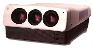
All of the alignment of these sets are quite similar in setup, we’ll concentrate more on the PRO 900 and 900x as they are more popular than the 880 and 881 models. The electronics of the PRO 880 are completely different from the PRO 900. The only common parts between the PRO 880 and the PRO 900 sets are the tubes and the lenses. The PRO 895 is identical to the PRO 900, for some reason Zenith switched model numbers as they were blowing out the last of the PRO 900 sets for dirt cheap sometime in 2002-2003. Let’s look under the hood of the set. The top cover comes off with a number of Philips screws. If the set has not been opened before, there are two screws that are screwed into the top lid from the BOTTOM half of the case, halfway down each side. It’s not required that these screws are put back in, as they make removing the lid with the set mounted on the ceiling a difficult task. Power supplies The front cover of the set comes off to expose the four power supplies and lenses.
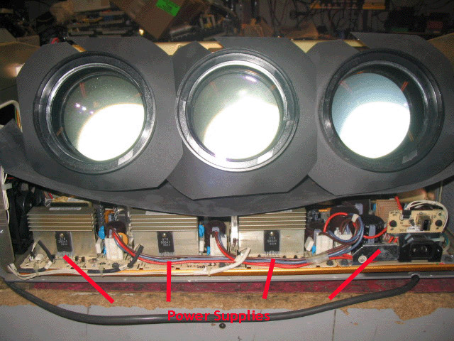
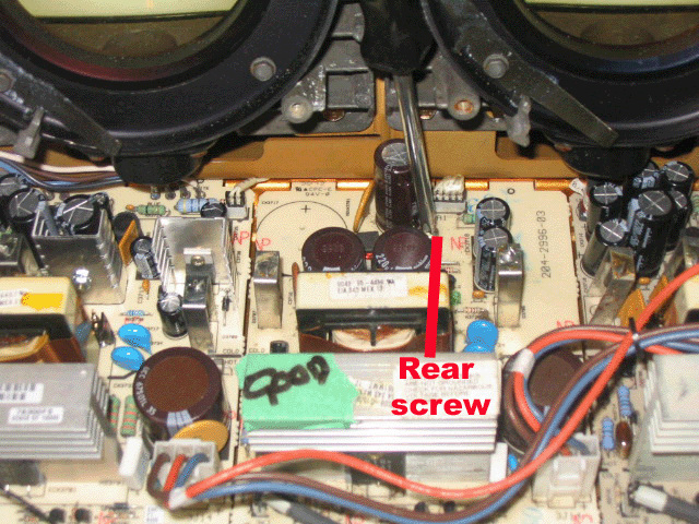
Note the plastic sheeting that is used to prevent dust from coming into the set from around the lenses. The lower plastic sheet directs the air flow from the fans over the power supply. I have had many sets come in that are missing this sheet, and I have not seen any increase in power supply failures due to these sheets being missing. The front of the set shows four individual power supplies. Each power supply has a green LED buried near the back of them that indicate operation of each supply. GENERALLY speaking, the power supplies in these sets are very reliable and do not need servicing. GENERALLY also, the green LED on each board will indicate proper operation of each supply, although I have had two cases so far where the LED has been lit on a supply yet one of the multiple output voltages has had a problem on the board. The power supply right behind the AC input board contains the standby power supply and is on from the moment the set is plugged in. The other three supplies are controlled by the power switch and will not turn on until the set is powered up. The far left board in the picture above is the high voltage power supply. While it should have the green LED turn on that board as soon as the set is powered up, a fault in the HV section will disable this power supply after a few seconds, so if this LED goes out shortly after the set is powered up, there most likely is a deflection or high voltage problem in the set, and the power supply is most likely OK. Each power supply is held into the chassis by two screws, but they each also have one Philips screw that hold the back of the board in place. One of the boards has two Philips screws in it. You need to remove the lens to access this rear screw:
The small board right above the AC input connection contains the front IR receiver. Each CRT tube pulls out from the front of the set. The lenses must be taken
off to access the bolts that hold the CRTs in place.
|
|
||||||||||||||||
 Zenith PRO
895x/900x
Zenith PRO
895x/900x
© Copyright CurtPalme.com. All Rights Reserved. |