 |
||||||||||||
| Home |
|
Products For Sale |
FAQs, Tips, Manuals |
Referral List |
|
Photo Gallery |
|
Links |
|
Contact Us |
|
|
||||||||||||||||||
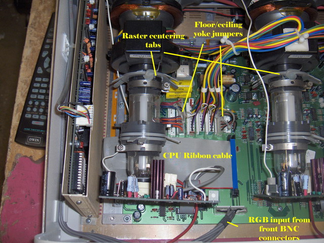
The CPU board contains all of the memories and setup menus and it controls the
operation of the whole projector. There is a Philips screw, one front and back
of the metal card cage to hold it to the chassis. The small white connector at
the top of the CPU board sends the IR signals from the front of the projector to
the CPU for control functions, the large ribbon cable from the bottom of the CPU
board controls the set functions. (see above picture).
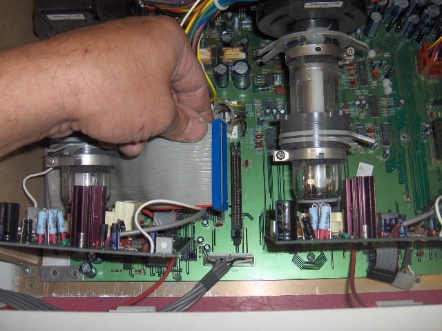
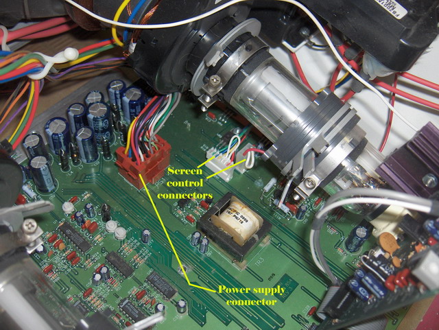
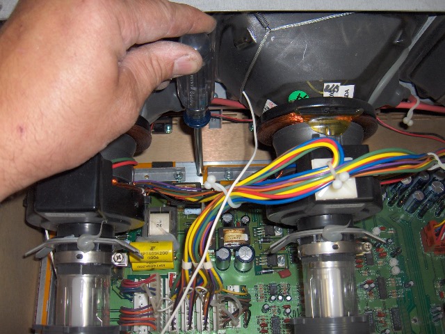
The CPU board comes out with the removal of the two connectors, and by loosening the Philips screws that hold the card cage to the chassis. The motherboard comes out from under the tubes without removing the tubes if you’re careful. Disconnect the various connectors that go to the motherboard as shown above and below:
When disconnecting the three yoke connectors that go to the CRT, note the sequence of orientation. DWIN colors one side of the connectors red, green or blue, depending on the tube they go to. If you mix the order up of the connectors when you reinstall, your convergence controls will not work properly. The motherboard is held to the chassis with four larger Philips screws, two at the back of the set and two underneath the tube yokes:
|
|
|||||||||||||||||

© Copyright CurtPalme.com. All Rights Reserved. |