 |
||||||||||||
| Home |
|
Products For Sale |
FAQs, Tips, Manuals |
Referral List |
|
Photo Gallery |
|
Links |
|
Contact Us |
|
|
|||||||||||||||||
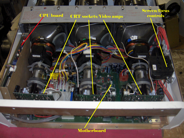
The tops of the projectors come off very easily to expose the internal workings of the projector. The DWIN 500 has a one piece cover, the 700 has a two piece cover. Internally, the 500 and 700 are very similar in layout, save for the CPU board that is located to the left of the red tube in the 600, and in the 500 it’s located between the G and B tubes. No parts save for the remote control will swap between the 500 and 700 sets due to the different tubes and circuits used. Once the top cover is off, the internals look like this:
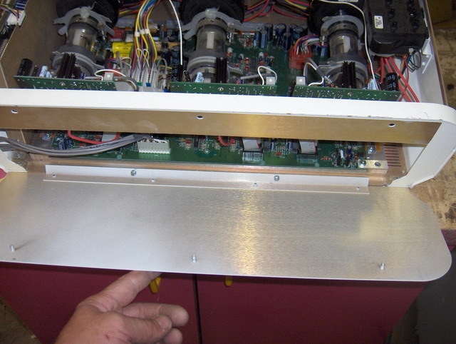
The back plate comes off with two screws and three nuts that are accessed from inside the top cover. That gives easy access to the CRT sockets that also contain the video amplifiers.
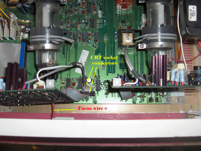
The CRT sockets/video amps are held in place on the tubes with a bit of hot glue, which comes off easily. There are two connectors that send the signals to the video board that unplug from the motherboard.
The red focus wire is soldered in place at the focus/screen controls., and can be cut and spliced with several layers of heat shrink tubing, as the wire carries 5000 volts, or may be unsoldered at the focus block. The video amplifiers do fail once in a while, usually resulting in a dim picture from one tube, or no picture at all.
The CRT tubes are relatively straightforward in the DWIN projectors. As with all CRTs, the set has the astig magnet set near the CRT sockets, but similar to the NEC projectors, the yokes have two metal tabs that move the raster/image around on the tube face significantly. The two metal tabs interact with one another, with one tab moving the picture in a vertical direction, the other in a horizontal direction, and careful adjustments will allow the raster to be properly centred or aligned on top of the other two tube images. The CRT tubes are held in place with four Allen screws, two that go through
the top metal plate covering the tube/lens assembly, and two more at the bottom
of the tube assembly. You’ll need a long Allen wrench to loosen the bottom
screws to either remove the tube(s), or to do lens toe-in for the projector
setup. The manual covers more of this in detail. See page 27 for the screw
locations.
|
|
||||||||||||||||


© Copyright CurtPalme.com. All Rights Reserved. |