| Author |
Message |
CRT_Ben
Joined: 28 Aug 2006
Posts: 1684
Location: Northern Virginia
|
| Posted: Sun Feb 03, 2008 10:11 pm Post subject: Marquee 9500 blue tube G2 problem...Help!! |
|
|
(edited to include recent troubleshooting info...and cut out the part where I'm crying like a baby  ) )
Hey guys,
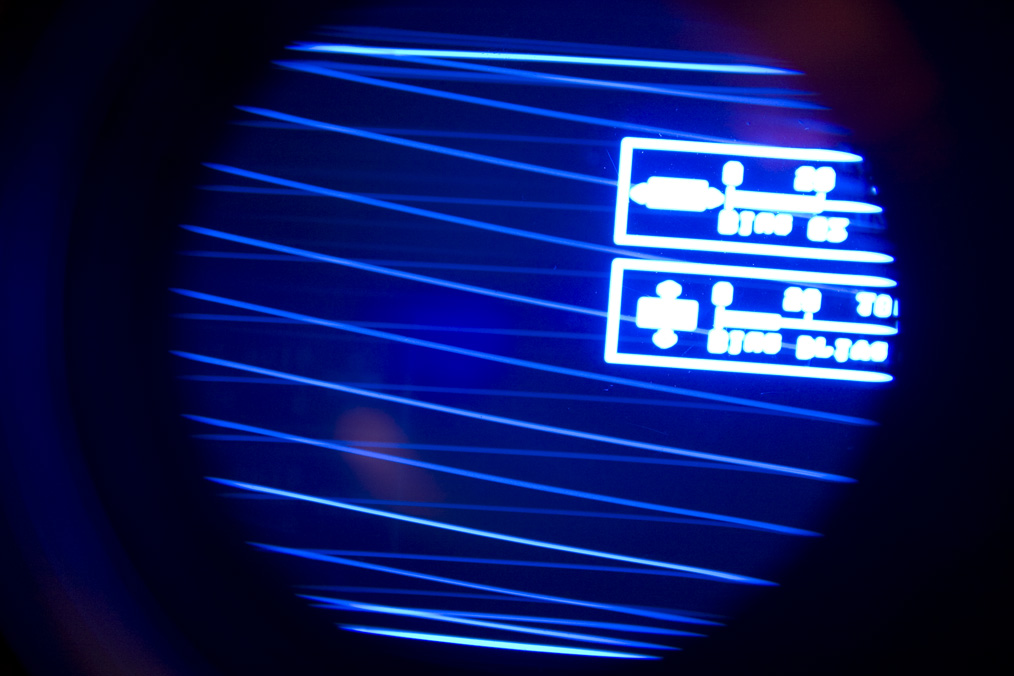
My PJ has been running like a top recently, so before my superbowl party yesterday I decided to tweak the astig and flare as it was looking a little off. I took the top cover off and moved the HV splitter/tube covers to tweak the astig/flare. When I started it up the blue tube problem presented itself (pic below). Other symptoms are the tube cutting in and out randomly, seems to be "off" more than "on" (this is looking on screen). However, when looking in the lens, those weird retrace lines are always there, and the pic is just really, really dim with occasional flashes of normal brightness.
I have reseated the VIM, focus board, HDM, neck board, CLM, HV leads, HVPS, LVPS. The problem seems to be independent of G2/drive controls.
I swapped the VIM and G2 leads from the blue to the green and the problem followed the wires (green got wacky, blue was fine). I didn't have time to swap the VIM/G2 leads independently to see which one was the problem.
Is the G2 signal delivered right from the HVPS? If so, is the G2 section potted?
Thanks!!
Ben
| Description: |
|
| Filesize: |
185.63 KB |
| Viewed: |
14078 Time(s) |
|
Last edited by CRT_Ben on Mon Feb 04, 2008 3:53 pm; edited 3 times in total
|
|
| Back to top |
|
 |
Zebu Fellenz
Joined: 21 Dec 2006
Posts: 2567
|
| Posted: Sun Feb 03, 2008 10:41 pm Post subject: |
|
|
Have you tried swapping the neckboard.
Try reattaching the HV lead.
|
|
| Back to top |
|
|
CRT_Ben
Joined: 28 Aug 2006
Posts: 1684
Location: Northern Virginia
|
| Posted: Sun Feb 03, 2008 10:43 pm Post subject: |
|
|
| Zebu Fellenz wrote: | | Have you tried swapping the neckboard. |
Hi Zebu,
I didn't swap the neckboard but I just swapped the Blue G2/VIM wires with the Green G2/VIM and the problem followed the wires, so now the green tube is acting up. So it's not the tube or neckboard, it seems to be a problem with the VIM or G2 control?? I'm going to reseat the LVPS and CLM...
|
|
| Back to top |
|
|
Zebu Fellenz
Joined: 21 Dec 2006
Posts: 2567
|
| Posted: Sun Feb 03, 2008 10:50 pm Post subject: |
|
|
Try swapping the G2 and VIM leads indepentent of each other, this will narrow down the problem.
Also check the VIM lead connection on the VIM, I had those come loose on my 8000 and it caused all sorts of problems, however I never had anything that looked like that. My guess is it's G2 related.
Erik
|
|
| Back to top |
|
|
CRT_Ben
Joined: 28 Aug 2006
Posts: 1684
Location: Northern Virginia
|
| Posted: Sun Feb 03, 2008 11:37 pm Post subject: |
|
|
| Zebu Fellenz wrote: | Try swapping the G2 and VIM leads indepentent of each other, this will narrow down the problem.
Also check the VIM lead connection on the VIM, I had those come loose on my 8000 and it caused all sorts of problems, however I never had anything that looked like that. My guess is it's G2 related.
Erik |
Hey Erik,
I was going to do this but ran out of time. As another kick in the teeth, after I reseated the CLM the projector stopped responding to the IR remote after initial power-on. After letting my blood pressure settle down we'll just watch it on my 27" TV  And I'll have to fix this later... And I'll have to fix this later... 
Also I forgot to mention that I'd already reseated the HV leads.
|
|
| Back to top |
|
|
CRT_Ben
Joined: 28 Aug 2006
Posts: 1684
Location: Northern Virginia
|
| Posted: Mon Feb 04, 2008 4:02 pm Post subject: |
|
|
|
Ok, I've edited the first post to add new information and much-needed coherency.
|
|
| Back to top |
|
|
CRT_Ben
Joined: 28 Aug 2006
Posts: 1684
Location: Northern Virginia
|
| Posted: Tue Feb 05, 2008 3:43 am Post subject: |
|
|
OK - I bought some contact stabilant tonight, and went through cleaning a bunch of contacts, pressing down on socketed chips, etc.
The set is responding to the remote again, which is good news - so now we're back to the original problem of the faulty G2 signal. I put the VIM wires back to their respective tubes but left the Green and Blue G2 leads swapped. The problem is still on the Green tube, so this is solely a problem with the G2 signal. Does this indicate a bad HVPS? Can the G2 section be fixed?
Thanks in advance,
Ben
|
|
| Back to top |
|
|
Nashou66

Joined: 12 Jan 2007
Posts: 16171
Location: West Seneca NY
|
|
| Back to top |
|
|
CRT_Ben
Joined: 28 Aug 2006
Posts: 1684
Location: Northern Virginia
|
| Posted: Tue Feb 05, 2008 4:12 pm Post subject: |
|
|
| Nashou66 wrote: | Take out the hvps and check the 560kohm reisitors see if they are all close to the same value for each G2(color). Also look and smell around to see if anything burned up on the HVPS. There are pics of modded HVPS on the Marquee group purchase thread to see what i'm talking about.
Athanasios |
Thanks Athanasios! I'll go scour the maint. thread for HVPS info 
Ben
|
|
| Back to top |
|
|
draganm
Joined: 08 Mar 2006
Posts: 8990
Location: Colorado
|
| Posted: Tue Feb 05, 2008 6:09 pm Post subject: |
|
|
| CRT_Ben wrote: | this is solely a problem with the G2 signal. Does this indicate a bad HVPS? Can the G2 section be fixed?
Thanks in advance,
Ben |
yes, the G2 section is on the un-potted side and can be repaired.
|
|
| Back to top |
|
|
CRT_Ben
Joined: 28 Aug 2006
Posts: 1684
Location: Northern Virginia
|
| Posted: Wed Feb 06, 2008 4:54 am Post subject: |
|
|
Ok, I didn't have time to find the multimeter tonight to measure the resistors, but I did open up the HVPS and snap a few pics.
It's kind of dusty...

and there's this white crap all over the circuit board near the potted section (it's in the lower left of the first pic, too) - not to mention a spider web!

I'm going to give this a good cleaning and bust out the DMM tomorrow. I'm not sure if the dust and white crap are causing any problems but I'd sure rather have a clean circuit board!
|
|
| Back to top |
|
|
1031

Joined: 22 Mar 2006
Posts: 657
Location: Finland
|
|
| Back to top |
|
|
CRT_Ben
Joined: 28 Aug 2006
Posts: 1684
Location: Northern Virginia
|
| Posted: Thu Feb 07, 2008 5:00 am Post subject: |
|
|
| 1031 wrote: | Those tree transistors (2sc4636) near 560k resistors are for g-2 adjusment, so look solderpoints closely and measure also those transistors.
That white "stuff" is normal..nothing to worry. |
Ok. I measured the "560k" resistors and they're pretty uniform, they fall between 635k and 660k. I also measured all of the smaller resistors and they seem to be within spec. I'm not sure how to measure the transistors - how would I go about doing that?
Thanks!
Ben
|
|
| Back to top |
|
|
1031
Joined: 22 Mar 2006
Posts: 657
Location: Finland
|
|
| Back to top |
|
|
1031
Joined: 22 Mar 2006
Posts: 657
Location: Finland
|
|
| Back to top |
|
|
CRT_Ben
Joined: 28 Aug 2006
Posts: 1684
Location: Northern Virginia
|
| Posted: Thu Feb 07, 2008 12:45 pm Post subject: |
|
|
| 1031 wrote: | http://www.allaboutcircuits.com/vol_3/chpt_4/3.html
Ok Use diode range on your multimeter, red lead to pin 1 black to pin 2 and then to pin 3
Pin1-pin 2 = 0.650v and pin 1-pin3= 0.679v
Those numbers doesent must be exactly same but close to 0.6-07v is ok.
other ways (black to pin 1 etc... and red and black lead between pins 2,3) should read OL
Pins are looked at front: 1,2,3 B,C,E |
Thanks for your help!! I have to leave for work now but I'll get to this tonight.
|
|
| Back to top |
|
|
CRT_Ben
Joined: 28 Aug 2006
Posts: 1684
Location: Northern Virginia
|
| Posted: Sat Feb 09, 2008 12:08 am Post subject: |
|
|
OK well everything seems to check out with the transistors, except there seems to be a reading between b1 and r3 - is this normal?
Here are my readings, r=red and b=black leads. In order from front (away from potted section) to back:
T1:
r1-b2=.593
r1-b3=.638
b1-r3=.925
everything else OL
T2:
r1-b2=.593
r1-b3=.640
b1-r3=.926
everything else OL
T3:
r1-b2=.592
r1-b3=.640
b1-r3=.916
everything else OL
|
|
| Back to top |
|
|
CRT_Ben
Joined: 28 Aug 2006
Posts: 1684
Location: Northern Virginia
|
| Posted: Sat Feb 09, 2008 6:06 am Post subject: |
|
|
Okay so go figure...after cleaning the HVPS boards and working on some other projects, I came back to the PJ and decided what the hell, I'll put the HVPS back together and fire it up. Wouldn't you know it works like a champ! Probably the only meaningful thing I did was put contact stabilant on that little HVPS daughter-board connector. I'd been wanting to do a setup from scratch so I did a reset and spent about 2-3 hours setting it up, it's been rock solid. Hopefully whatever was "broken" has been fixed, I'm not gonna look the gift horse in the mouth 
Thanks for all your help guys!
Ben
|
|
| Back to top |
|
|
1031
Joined: 22 Mar 2006
Posts: 657
Location: Finland
|
|
| Back to top |
|
|
CRT_Ben
Joined: 28 Aug 2006
Posts: 1684
Location: Northern Virginia
|
| Posted: Wed Feb 13, 2008 2:47 am Post subject: |
|
|
Okayyy...
Well, tonight I was watching the PJ and all of the sudden the blue tube went out. No nasty noises, nothing, just disappeared. At this point I'm figuring that my magic "fix" of cleaning contacts wasn't quite enough 
So I walk around the front of the PJ and I find that the raster is slightly lit, as normal, in the blue tube, but it's like it's not receiving a video signal. None of those crazy retrace lines and flickering I was seeing before. I ramp the G2 up and down and the raster responds normally. I unplugged the PJ, pulled the VIM, and swapped the green and blue leads. Fire up the PJ and lo and behold the blue and red light up, but no green! Green raster is softly, normally lit, just no video. For one last troubleshooting data point, I swapped the blue and green input BNCs to eliminate a possible source problem.
SO! I guess I have (had? still hoping the G2 problem is gone) two problems that have similar symptoms but are probably unrelated? Still I find it VERY strange that the blue G2 would act up, and suddenly after, the blue channel on the VIM would act up. And I know it's the VIM because the source checked out when I swapped the input BNCs, and the blue tube worked fine when hooked to the Green channel, so it's not the neckboard. I don't suppose that a problem with the blue tube or neckboard could cause the input signals to the tube to act up?? 
Thanks for all your help, guys!
Ben
|
|
| Back to top |
|
|
|
|


