|
As this forum is rarely used anymore, we've locked it. Feel free to browse and read. Questions? Please reach out to us directly. Cheers! |

|
 |
|
|
| Author |
Message |
Nitmoe

Joined: 10 Jan 2008
Posts: 60
Location: Iowa, USA
|
| Posted: Sun Jan 20, 2008 10:30 pm Post subject: Mods on ECP 4100 |
|
|
I've been looking around trying to figure out what I can do to improve my 4100. I want to maximize performance from this little guy, and I'm having some trouble. Any help or leads would be greatly appreciated. So far, this is what I have found.
Lenses: HD-145 (non-color corrected, unless replacing tube glycol with clear) Is this correct? This is a 7" air coupled ES set, will these lenses fit properly?
Retrace issue: http://archive.avsforum.com/avs-vb/showthread.php?threadid=282004
Focus issue: http://www.curtpalme.com/ElectrohomeECP_Layout3.shtm
(According to this, I need a 55 meg ohm 2 watt flameproof resistor or equivalent series of smaller size for 07MS)
In another thread someone said a 61 meg ohm resistor provided more accurate focus, so what is best?
Capacitor upgrades: (taken from "ECP Wisdom" in thread https://www.curtpalme.com/forum_archived/viewtopic.php@t=5959.html )
RGB Input Board
=========================
2 power supply caps:
2200uF 50v Panasonic FC Series 105 degrees
3 power decoupling caps:
330uF 25V Panasonic FC Series 105 degrees
7 ceramic power bypass caps:
0.1 uF 25V film caps WIMA polystyrene
9 signal coupling caps:
150uF 100V
3 main output coupling caps:
330uF 25v same as above. Parallel on underside of board with 0.22uF 16v)
Neck Board
==========
33uF 250v Panasonic EB
Bias/Focus Board
================
100uF 250v Panasonic EB
Use OS-CON capacitors for signal coupling and low voltage power supply buffering.
If anyone out there can help in any way, that would be great. Please let me know if I have missed anything, or if any of this is incorrect. I know this is a lot to go through for an older set, but it's what I have, and I want to make the most of it.
Also, if anyone has the lenses I need, please let me know, Thanks.
|
|
| Back to top |
|
 |
Nitmoe
Joined: 10 Jan 2008
Posts: 60
Location: Iowa, USA
|
| Posted: Mon Jan 21, 2008 12:49 am Post subject: |
|
|
|
Okay, so it looks like when the tubes were upgraded to the 07MS the resistor was replaced with a nice high quality one, which is printed 44.8 Mohms, with a standard looking 10 Mohm +/- 5% resistor, so I'm not going to mess with it. Also, I have been looking at digikey, and this is probably where I will get the caps, unless someone knows of a better place.
|
|
| Back to top |
|
|
Curt Palme
CRT Tech
Joined: 08 Mar 2006
Posts: 24396
Location: Langley, BC
TV/Projector: All of them!
|
| Posted: Mon Jan 21, 2008 1:21 am Post subject: |
|
|
Before you spend a messload of time on the caps, check your focus first. If you see scanning lines at 1080i or maybe 720p if the tubes are really new, then sure, try recapping. If you ahve overall soft focus, it means the tubes hvae run a long time, and no matter how much you recap, you won't get your focus back. THat means you'll never see any improvement in minor changes in the video circuits.
But hey, if you proceed, let us know if you do really see a difference.
|
|
| Back to top |
|
|
Nitmoe
Joined: 10 Jan 2008
Posts: 60
Location: Iowa, USA
|
| Posted: Mon Jan 21, 2008 3:39 am Post subject: |
|
|
Hmm, well this certainly is a little soft at 720p. I have had a lot of trouble with 1080i, which is what I wanted to run initially, so I can't really say how it looks at that res, I'm still going to play some more. I have had it running 1080p without an issue, other than it is obviously going to be soft at that res. Still, I'm not sure how long these tubes have been run, especially in standby. There is very minimal phosphor burn, of coarse that can often mean very little. I had hoped that at least a couple of the caps here could make a difference, and I was hoping someone could point me in the right direction of which to try first. I thought maybe the focus board and the neck boards? Still, either way, I am more curious about the lenses. Will the HD-145 lenses fit, and is it worth the upgrade?
If I do any of the cap updates, I will do each one individually, so that I can see where the benefit comes from, if any.
|
|
| Back to top |
|
|
Nitmoe
Joined: 10 Jan 2008
Posts: 60
Location: Iowa, USA
|
| Posted: Mon Jan 21, 2008 9:25 am Post subject: |
|
|
|
A couple of notes here. First of all, I realized that I had even touched the astigmatism controls yet. Not really sure how they got to be so incredibly far off, but it's taken care of now. Completely took care of the soft green issue I was having, and as a result sharpened up the overall image pretty well. I found out that this PJ doesn't like 1080i at vertical refresh of 30 or less. I bumped it up to 36, this seems to work best. Still not all that impressive, but it is an ES set. I'm almost ready to buy the HD-DVD drive for my HTPC, but I need a little more time. It's already pretty difficult to watch anything other than my set, I don't want to push it too much. Most people I know won't come off of their SD tv sets, and only talk of LCD as a possible replacement. Pretty sad, I guess I'll just never leave the house.
|
|
| Back to top |
|
|
WarLord
Joined: 08 Feb 2007
Posts: 14
Location: Toronto, Ontario, Canada
|
| Posted: Wed Jan 23, 2008 6:19 am Post subject: |
|
|
I have analyzed and tried many different mods for ECP except for HD-145 lenses so I cannot comment on this one.
Retrace issue mod: There were a lot of discussions about this mod on AVS. I have done this mod and I do not recommend doing it. This mod will remove the vertical brightness bar in low band mode and it will remove unwanted light in high band (in high band the bar spreads across the whole screen). Unfortunately this will also introduce the darkening and lost detail at the left. Although not easily visible with eyes you would be amazed how much detail you loose if you check the waveform with oscilloscope. In fact in higher refresh rates you will loose detail over half of the screen. There were some attempts to improve the situation by changing G1 circuitry, but this has not produced satisfactory results. What nobody realized is that the problem was not limited to slow G1 circuit. By doing this mod you inadvertently also affecting the contrast circuit and basically reducing the contrast level to zero for every scan line. Contrast circuit in ECP is not designed to be turned on and off that fast and if you take into account that the contrast signal goes through the low pass filter on video control module, the result you get is the darkening of the picture at the left. I personally was not satisfied with or without this mod so I designed my own solution that took care of both problems: completely eliminate the brightness band and in the process not to loose any detail, but it is a lot more complicated than just changing the jumper and requires additional components and serious taping into the ECP circuitry.
Just think why Electrohome originally have not done this mod?
So you choose: do the mod and loose a lot of detail on the left or live with little of unwanted light during retrace.
Focus issue: The best mod for ECP if you have older BIAS module. Changing this rectangular resistor will instantly restore the focus voltage to what it was supposed to be. I wish I knew about this mod when I first got my ECP in 1997 could have saved me a lot of headache and frustration. Putting additional 10M ohm resistor is only necessary if you are using 07MS tubes.
Capacitor upgrades: Do not waste your time on this one. The most stupid mod ever made for ECP. I was skeptical about this mod even before I tried it. I verified the signal at appropriate points with oscilloscope after changing some of the caps and there was no difference what so ever. Most if not all comments about amazing difference this mod does are based on eye observations (hardly a precisely calibrated scientific instrument) If you analyze the schematics you will see that the caps mentioned in the list are only account for about a third of all the caps in the video chain, I wonder what about the rest of the caps in the video chain?
Voltage filtering caps on the Video Output module and Input module are sufficient by itself and changing them will not improve the signal quality. The voltage rails of this projector are extremely polluted by EMI emissions from numerous SMPS (switch mode power supplies) present in the projector and I am not just talking about LVPS and HVPS, there are additional two SMPS present in the back of the projector. The chassis of the projector resonates by itself and puts a lot of noise into video signal through the ground. No matter how good filtering capacitors are, the effect they will produce will be negligible if any and large capacitors are not very good in filtering EMI. I tried to increase the value of the caps with no results (Verified with the oscilloscope). The only way to stabilize the voltage that goes to the video chain is to isolate the video chain from the chassis completely (impracticable) or to stabilize it at the source near SMPS (very difficult).
Bias/Focus Board cap change -100uF 250v Panasonic EB: This is my favorite. I think the person who designed this mod understands nothing in electronics (read carefully through archives and you will know who it was). This is a spot kill capacitor. It has nothing to do with the video chain or the signal quality. The purpose of this cap is to hold the voltage that will instantly reduce or kill the electron beam through G1 circuit after you turn off the projector so you do not develop a spot burn in the middle of the tube. Increasing the value of the cap will only increase the time that the beam will be down after you turn off the set. I am sure the gravitational influence of a passing moon will produce more effect on video signal quality than changing this capacitor (at least gravitational influence of the moon is scientifically proven).
Fan mod: There were many deferent solutions to quiet the noisy fans in the ECP; change the fans for modern quieter ones; reduce the speed of the fans by adding a series resistor (bad idea); cutting holes in side panels or removing the side panels completely. To reduce the noise from the fans I simply reversed them. I think it can be done if the projector is used in ceiling mounted configuration, but I do not recommend doing it because I do not know the long-term effect of reversing the airflow since I have not used the projector much after doing the mod.
Video cable mod: This mod resolves the issue with bad contacts of the cable that caries video signal from the motherboard to each of the neck boards. The cable is known to develop bad contacts especially in older units. It involves soldering the cable directly to the boards. The down side to this mod is that soldering the cable at the motherboard end is complicated because it requires removal of the tubes and it also defeats the modularity aspect of this projector in case some day you will need to change a neck board. It may be easier just to reseat the cable a few times than mess with soldering. Bad contacts at this cable may also exaggerate vertical line problem (another ECP design flow).
Isolating back panel of RGB Input module: This will improve the situation with very fine vertical line that can be seen to the left of the center of the picture. It can appear on all three tubes or only on some of them. The line is a result of poor design of horizontal deflection drive circuitry. It is actually the transients that transfer to the video signal through the chassis. It is more visible on some units than the others and probably defined by the quality of the connections between internal boards and cables but the problem is present on every ECP. Eliminating the line completely will require isolating horizontal deflection drive circuitry from the chassis or totally redesigning it, both of which is impracticable (better get a different projector).
The mod is very simple: all you need to do is wrap the sides of aluminum back panel of RGB input module with electrical tape so it does not touch the chassis and remember not to bolt the module to the chassis after it. I was skeptical at first, but after doing it I can confirm that it will significantly reduce the line, but will not eliminate it. This mod is only useful if you can see the line and it really bothers you.
Coke bottle effect: this is not really a mod but rather a known ECP geometry design flaw and as far as I know there was no solution for this one. The only way to remove the effect is to play with green convergence and then converge the other colors on green.
To maximize the performance of the projector I would do the following and I am sure you already know most of it:
Remove clean and inspect every board in the set including power supplies. Re-seat all the chips in their sockets and all connectors that present in the projector; and yes it is time consuming. When inspecting look for bad connections or cracks in solder where power components and connectors soldered especially the large ones. Pay particular attention to vertical deflection and horizontal regulation module, three power deflection modules and LVPS. This will resolve a lot of intermittent behavior problems that are so common in these old sets. Check for burnt or heavily discolored components. Tiny pots on the back of each neck board sometime may become intermittent and cause random brightness changes or flashes of the corresponding color. In this situation it will be necessary to clean them by turning a few times or to replace if cleaning does not help. Maximize the picture on the tube face and center the raster. Run projector at 800x600 anything higher and the picture will become softer. Actually I was able to see the scan lines at 1024x768 but only with new tubes. Reduce refresh rate as low as possible without seeing flickering, if it starts flickering increase refresh to the next value. I found that my ECP looks best at 800x600 at 75Hz. Replace Dallas chip if it is old and intermittent. If you have Acon installed remove the board, you can better converge without it manually. Not only the board will additionally load already overloaded LVPS,but it may also introduce unwanted noise to the video signal from the SMPS located on the board which can be seen as barely visible horizontal waves randomly running up and down the screen. Each wave corresponds to single pulse the SMPS produces. By the way every SMPS located inside the projector introduces noise in the form of the random waves in its own frequency but you cannot do much about them and that is one of the reasons why ECP known to have a noisy picture.
If you are a little more advanced in electronics I recommend checking every electrolytic capacitor in the projector with the ESR meter. I am sure you will find a few dried or bad electrolytic caps especially in the LVPS if it is a high hour unit (evident by brown burning spots on green pcb). Dried caps usually will be located near high power components like power resistors or power transistors. Leaving bad capacitors unchanged may reduce performance and in worst situation may lead to component failure. Check for correct voltage on power rails from LVPS, if it is slightly off you can adjust it with pots located on the power supply. If the power supply was heavily used I would check the condition of a large power resistor R85 in the LVPS should be 18K Ohms, the surrounding electrolytic capacitors almost certainly will be dry. You can even try to relocate the resistor away from the cluster of electrolytic capacitors it seats in, though you need to be creative mounting it in a different spot. I also noticed that most Rubycon electrolytic capacitors used in this set have higher ESR values than one would expect from the similar caps (especially 47uF, 4.7uF, 10uF)
Please if you decide to do anything from the above do it at your own risk, you can easily damage something without even knowing it. If you do this maintenance without destroying something in the process, it will be by far more useful to the projector than most of these mods.
Michael
PS. This is just my opinion, others may be different.
|
|
| Back to top |
|
|
Nitmoe
Joined: 10 Jan 2008
Posts: 60
Location: Iowa, USA
|
| Posted: Wed Jan 23, 2008 8:54 am Post subject: |
|
|
|
Well I probably won't be messing with anything in the video chain now. There are some noise issues I had hoped to resolve, but apparently there isn't a reasonable approach to eliminating this. I will be removing the ACON board though, I don't use it anyway. Thanks Warlord for the lengthy post, probably save me a little wasted time. I had planned on going through the power supply anyway, most electronics I have worked with have bad or failing caps in the PS.
|
|
| Back to top |
|
|
Andrew Low
Joined: 19 Apr 2007
Posts: 28
|
| Posted: Wed Jan 23, 2008 4:07 pm Post subject: |
|
|
Michael / WarLord - great post.
It has been a long time since I had my ECP - but I do have experience on two areas which you commented on, so allow me to follow up on them.
| WarLord wrote: |
Fan mod: There were many deferent solutions to quiet the noisy fans in the ECP; change the fans for modern quieter ones; reduce the speed of the fans by adding a series resistor (bad idea); cutting holes in side panels or removing the side panels completely. To reduce the noise from the fans I simply reversed them. I think it can be done if the projector is used in ceiling mounted configuration, but I do not recommend doing it because I do not know the long-term effect of reversing the airflow since I have not used the projector much after doing the mod.
|
My experience here was modifying the side panels to remove the 'grill' made the biggest difference. In my ECP unit, 3 of the fans blew air 'in' and 1 was 'out'. I did additionally replace all 4 fans with an equivalent, but quieter (and new), fan - this made an additional incremental improvement, but it was more subtle.
| WarLord wrote: |
Video cable mod: This mod resolves the issue with bad contacts of the cable that caries video signal from the motherboard to each of the neck boards. The cable is known to develop bad contacts especially in older units. It involves soldering the cable directly to the boards. The down side to this mod is that soldering the cable at the motherboard end is complicated because it requires removal of the tubes and it also defeats the modularity aspect of this projector in case some day you will need to change a neck board. It may be easier just to reseat the cable a few times than mess with soldering. Bad contacts at this cable may also exaggerate vertical line problem (another ECP design flow). |
My ECP had some issues with the pins on the neck board getting dirty enough to affect the signal. This manifested itself as variable brightness on the red tube (lines). Simply cleaning the connection corrected the problem completely. In this case - I agree completely with your advice.
A 3rd bit of advice - one I wish I had followed myself. The ECP isn't that bright a machine, and I was running it on a 80"x45" screen. Painting the room (including ceiling) a dark gray helped improve the picture quality - but had I chosen to run it on a smaller screen (72" wide x 40.5" high) it would have been much better - a brighter, punchier image.
80x45 = 3600 sq inches
72x40.5 = 2916 sq inches
A ~24% difference in area is a big change in terms of how much screen you're trying to light up.
|
|
| Back to top |
|
|
jcmccorm
Joined: 15 Jan 2008
Posts: 21
|
| Posted: Wed Jan 23, 2008 10:38 pm Post subject: |
|
|
Michael, good post, and I agree with most everything except for a couple of items.
As Andrew pointed out, simply cutting the grill out of the chassis sides in front of the fans makes a big difference in the fan noise. I don't believe that anything else needs to be done.
As for the retrace issue, the described mod only affects the G1 voltage and I don't see how it can effect the contrast circuitry. G1 is slow to come back so the raster gets darkened on the edge. This should be well out of the image area anyway. There are other ways to fix the issue, but none as simple as this, with the only problem being a slight loss of available raster (which shouldn't be used anyway).
And BTW, the focus board cap change was my favorite too  I looked at the schematics and couldn't see the benefit. I don't remember if I changed that cap or not (wouldn't be surprised if I did though). I looked at the schematics and couldn't see the benefit. I don't remember if I changed that cap or not (wouldn't be surprised if I did though).
Cary
|
|
| Back to top |
|
|
Nitmoe
Joined: 10 Jan 2008
Posts: 60
Location: Iowa, USA
|
| Posted: Thu Jan 24, 2008 5:01 am Post subject: |
|
|
|
Thanks guys, I was hoping there was someone out there that had some experience with mods on these. Removing the fan grills sounds like a good idea, and so I probably will get that done before I set this thing up in a more permanent setting. I am currently running this in a guest bedroom where I am staying, but it won't be long before I take it to my house. Right now I am running on a vinyl window shade (yippee) and my image measures at 58.5 xi 33, so 1930.5 square inches, and produces a nice bright image. The screen I had planned to use at home is 80" wide, but I might consider scaling it down a little (maybe). The room it would be in is totally blacked out, with very little room reflection (unlike my current situation). My only concern right now is convergance. As it has been stated this thing is a little drifty. Side to side I can get the CRT's lined up pretty well, but they are off drastically top to bottom. I was wondering if someone could tell how to adjust vertical position. Certainly there should be a trim pot somewhere to control this, as opposed to using the electronic convergance to correct it. The red has to be about 10% to high when reset to default. Any tips on other aspects of alignment either with trimpots, or mechanically would be helpful. I have tried using the pivot bolt in conjunction with the other two Scheimpflug adjustment bolts, and this made little if any difference once corner to corner focus was restored.
|
|
| Back to top |
|
|
WarLord
Joined: 08 Feb 2007
Posts: 14
Location: Toronto, Ontario, Canada
|
| Posted: Fri Jan 25, 2008 5:38 am Post subject: |
|
|
Nitmoe, There is no vertical position adjustment in ECP, The only way to adjust it is to use convergence, It is stable in this direction and it is normal for the picture to be off center vertically after reset.
Andrew and Cary, I absolutely agree that cutting the grill out or removing the side panels is the best and simplest way to reduce the noise and it works perfectly, its just was not aesthetically appealing for me. I have done it as an experiment and as I said I do not recommend doing it my way.
Regarding retrace issue: I have extensively tested this mod. To see the difference between unmodded and modified versions instead of moving the jumper I installed a switch with one position as unmodified state and another as modified (equivalent of moving the jumper). This allowed me to see the difference between two states without removing eyes from the screen while the projector was operational. I displayed gray field and was disappointed to see a lot of lost detail in modded version while switching fast between the two positions. Later scope observations taken at the neck board also confirmed this. Waveform taken at the neck board of a single scan line with the gray field displayed resembled a waveform of capacitor charging, it is rises very fast at first, then flattens but still keeps to rise and takes very long time to reach its maximum level. In higher refresh rates the darkening of the picture (or rising of the signal) continued well beyond center of the screen. It is not easy to see without directly comparing it to unmodded version because the change is gradual and very smooth.
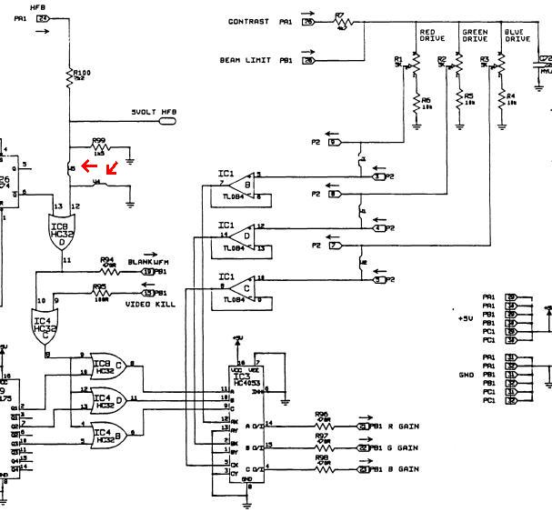
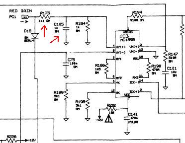
I will explain how it also affects contrast circuit. As can be seen on the schematic of Waveform module below, the mod requires to move the jumper from W4 position to W5 as marked by red arrows, this allowed modified BLANK WFM signal to go to BIAS module and to G1 circuit. No problem here except that G1 is slow. What was overlooked is that the same signal also went through series of OR gates to IC3 where it mixed with Contrast signal for each color. At the output of IC3 contrast signal (gain) began to fall to zero for each horizontal retrace. Then new and modified contrast signal went to Video Control module (second picture), where before entering IC3 in case of red color (other colors similar) it went through network of R173 and C105, which form a low pass filter. Now imagine changing the state of contrast signal for every scan line, the result I described above.
I am convinced that this was the reason why E-home decided not to do the mod and actually removed the jumper option in later boards.
Michael
| Description: |
|
| Filesize: |
48.21 KB |
| Viewed: |
8309 Time(s) |
|
| Description: |
|
| Filesize: |
21.07 KB |
| Viewed: |
8309 Time(s) |
|
|
|
| Back to top |
|
|
jcmccorm
Joined: 15 Jan 2008
Posts: 21
|
| Posted: Fri Jan 25, 2008 7:17 am Post subject: |
|
|
Hey Michael, I stand corrected! Good post. I've got a buddy with an ECP set up that would be interested in fixing this. Thanks.
Cary
|
|
| Back to top |
|
|
DLK
Joined: 20 Aug 2007
Posts: 7
Location: Monrovia, AL
|
| Posted: Wed Jan 30, 2008 9:56 pm Post subject: |
|
|
Michael,
Thanks for the detailed observations on the retrace modification. My first impulse is to disable the effect that BLANK_WFM has on the contrast as part of the modification. I want to understand the consequences of leaving the cathode modulation at its display level while G1 is biased to cutoff, however. I'm also still interested in speeding up G1 on the neck boards. As usual, the time necessary for me to perform these hacks is limited.
My viewing experience have been improved by applying the original modification, particularly if the projector is operating in low band. Perhaps this is because I use an HTPC with Powerstrip to align a subset of the available raster for viewing. I can avoid the worst part of the raster this way.
-Dan
|
|
| Back to top |
|
|
WarLord
Joined: 08 Feb 2007
Posts: 14
Location: Toronto, Ontario, Canada
|
| Posted: Thu Jan 31, 2008 5:17 pm Post subject: |
|
|
Dan,
I just opened the original thread A fix for the Electrohome ECP... and saw that it was you who tried to speed up G1 circuit. Nice work by the way.
Can you explain me one thing; In this thread when you were doing the jumper mod": | DLK wrote: | | I lifted the pin instead of cutting the trace. It took all of 5 minutes. |
I have always been puzzled how you were able to lift the pin on 06p board without damaging the pin itself? I tried to lift the pin but could not do that and had to cut the trace instead.
After analyzing what jumper mod was doing to the circuitry and what was necessary to achieve I came to conclusion that there is no need to speed up G1 circuit. I had excellent results by making the length of the pulse that goes to G1 (BLANK_WFM) adjustable, this allowed to start rising G1 even before the retrace is finished, which in turn solves the problem of G1 being slow. The down side to this approach is because the retrace time is different in low and in high band, it may be necessary to readjust the length of the pulse when switching between the bands. Since I only use my projector in high band I dont have any problem with that. I avoided effect on contrast by installing the necessary circuitry directly into BLANK_WFM line.
I am against moving the picture with external sources to avoid darkening because it will introduce its own negative side effects.
Michael.
|
|
| Back to top |
|
|
jcmccorm
Joined: 15 Jan 2008
Posts: 21
|
| Posted: Fri Feb 01, 2008 6:27 am Post subject: |
|
|
Hey Michael, do you find that the contrast circuit recovers in time as well?
If it does, would you mind posting your mod back in that original thread (if it's still open)?
Cary
|
|
| Back to top |
|
|
DLK
Joined: 20 Aug 2007
Posts: 7
Location: Monrovia, AL
|
| Posted: Fri Feb 01, 2008 4:03 pm Post subject: |
|
|
| WarLord wrote: | | I have always been puzzled how you were able to lift the pin on 06p board without damaging the pin itself? |
I use a manual solder sucker to remove the solder from the barrel. When I get it clean enough, I grab the end of the pin that is sticking out with a pair of long nose pliers. I gently work it back and forth sideways, where I can pop it loose from the small amount of solder that remains. Sometimes I will clean out the barrel, then reheat and move the pin around so it's not touching the wall of the barrel. Sometimes some solder wick is useful to aid in cleaning out the barrel. Anyway, once the pin is loose, I can fish it up out of the barrel with some tweezers. (sure beats rework on a BGA package )
It looks like it would be simple to lift and ground IC7 pin 10 (-06 waveform generator) or IC4 pin 10 (-05 waveform generator) as an addendum to he original Cary mod. This would remove BLANK_WFM's influence on the contrast. If it doesn't break something else. It would be nice to not have to do a G1 speedup mod, as it's more involved than hacking the waveform generator.
-Dan
|
|
| Back to top |
|
|
WarLord
Joined: 08 Feb 2007
Posts: 14
Location: Toronto, Ontario, Canada
|
| Posted: Sun Feb 03, 2008 5:07 am Post subject: |
|
|
Unfortunately A fix for the Electrohome ECP... thread long since became read only and seats in AVS archives. If I had more time I would have prepared a detailed post on the issue, but because nobody interested in these projectors now days its just not worth the effort. I will give a brief description of the mod here instead.
Grounding IC7 pin 10 or IC4 pin 10 wont work here as this line is used for blanking to function properly.
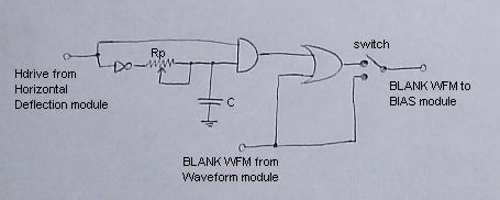
First picture shows the theoretical circuit. Hdrive signal enters the circuit and becomes converted to pulse with adjustable duration, then it combines with original Blank Waveform signal in OR gate and goes to BIAS module. Potentiometer changes the duration of the pulse and allows precisely adjust the point at which to start to rise G1 voltage. Switch is used to choose between modded and unmodified versions. It is not really needed, but I find it to be very useful to see the difference the mod does and it also allows returning the board to original unmodded condition without soldering. Instead of using 5volt Horizontal Flyback signal as it was in jumper mod I used Hdrive (Horizontal Drive). Since Hdrive precedes HFB it allowed to cutoff G1 before the scanline is finished and eliminated unwanted vertical bright line at the far right side of the raster. Hdrive is not present by default in Waveform module and it will be necessary to add a wire that goes to Horizontal Deflection module where Hdrive is available.
Contrast circuitry remains completely untouched by this mod and works exactly as it was designed by E-home.
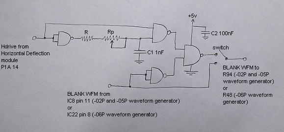
The circuit in the first picture is easy to understand but not practical to build: It uses three different gates, which will require three separate chips. Second picture shows the actual circuit. It functions exactly as the circuit in first picture but implemented with four NAND gates, which will require only one Quad 2-Input NAND Gate chip and several other components.
I tested the circuit on ECP 3000 (50-1873-02P Waveform module with 4011 chip) and on ECP 4000 (50-1873-06P Waveform module with 74LS132 chip).
4011 is CMOS Quad 2-Input NAND Gate and works perfectly for ECP 3000 but may prove to be a little slow for ECP 4xxx. I dont remember if I verified it with ECP 4000 as it was a couple of years ago when I was playing with it.
For ECP 4000 I used 74LS132 (this is what I had available at the time), which is fast TTL family Quad 2-Input NAND Gate but it is not perfectly compatible with ECP circuitry and may be unstable. Although it works well on my ECP 4000 I would not recommend using it.
I was thinking that the best type to use would be from 74HC family (74HC00). It is a high-speed CMOS device and will be perfectly compatible with ECP circuitry as it is exactly from the same series of chips that Electrohome used throughout the set.
The value of potentiometer depends on model of the projector and on what chip is used. I settled for 10 kOhm for ECP 3000 and 2 or 3 kOhm for ECP 4000. If there is not enough range then the value needs to be increased, if the pot is too sensitive then it needs to be decreased accordingly.
Resistor R prevents NAND gate from overloading by capacitor when the pot is in its lowest position (when it virtually disappears from the circuit). Although I have not installed this resistor it is better to do it to be safe. I guess the value should to be in a range of about 200-300 ohm.
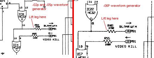
It is necessary to lift the leg of resistor R94 (or R48 for -06p board) as shown in the last picture and solder the output of the circuit to the lifted leg.
If jumper (or trace for 06p board) was moved by previous jumper mod it needs to be returned to its original location.
Now it is possible to center the raster on the tube face and the image within the raster as its supposed to be.
As I explained in my previous post it might be necessary to readjust the pot when switching between the bands or it is possible to set the pot somewhere in between as a compromise. I dont see any difficulty to make it work for both bands independently, by installing two identical circuits, one for low band and another for high, and then an automatic switch that will choose one of the circuits for appropriate band, but this will complicate the design and increase the number of components (may as well be enough to get an engineering degree).
If necessary I can post pictures of finished boards, since I already by pure coincidence (Inno!) have them on my computer.
Michael.
| Description: |
|
| Filesize: |
11 KB |
| Viewed: |
8096 Time(s) |
|
| Description: |
|
| Filesize: |
22.67 KB |
| Viewed: |
8096 Time(s) |
|
| Description: |
|
| Filesize: |
22.66 KB |
| Viewed: |
8096 Time(s) |
|
|
|
| Back to top |
|
|
|
|
|
|
|
You cannot post new topics in this forum
You cannot reply to topics in this forum
You cannot edit your posts in this forum
You cannot delete your posts in this forum
You cannot vote in polls in this forum
You cannot attach files in this forum
You can download files in this forum
|
Forum powered by phpBB © phpBB Group
|
|


