| Author |
Message |
incova
Joined: 27 Nov 2006
Posts: 789
Location: london
|
| Posted: Sun Aug 19, 2007 11:05 pm Post subject: same result |
|
|
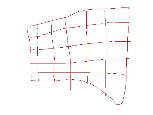
ok removed it and tried with normal power, same result except now I have no green or blue and a massively distorted red even with registration there is no way I could converge the red.
| Description: |
|
| Filesize: |
16.27 KB |
| Viewed: |
6886 Time(s) |
|
_________________
The more I learn
the less I know.
|
|
| Back to top |
|
 |
incova
Joined: 27 Nov 2006
Posts: 789
Location: london
|
| Posted: Sun Aug 19, 2007 11:09 pm Post subject: green |
|
|
The green tube was the same but I tried the green and blue cut off and no luck the tubes seem to not want to respond. The backs of all the tubes light up I assume thats good but dont really have a clue right now, the pj says its fine on code 30?
_________________
The more I learn
the less I know.
|
|
| Back to top |
|
|
incova
Joined: 27 Nov 2006
Posts: 789
Location: london
|
| Posted: Sun Aug 19, 2007 11:11 pm Post subject: red tube |
|
|
That picture is with nothing inputting into the pj thats meant to be a test pattern.
_________________
The more I learn
the less I know.
|
|
| Back to top |
|
|
papalek

Joined: 08 Mar 2006
Posts: 1536
Location: Longs SC
|
| Posted: Mon Aug 20, 2007 1:57 am Post subject: |
|
|
Swap the black wire that goes between the RGB card and the neck boards from red to blue and see if blue lights up. You can do this with the PJ on and then you will be sure the wire has a live feed. Might be a bad neck card or bad RGB board.
_________________
My current list of PJ's AmPro 1 1/2-4600,4200, 1/2-3600,2600.
I do love my AmPro's
|
|
| Back to top |
|
|
incova
Joined: 27 Nov 2006
Posts: 789
Location: london
|
| Posted: Mon Aug 20, 2007 12:25 pm Post subject: swapped wires |
|
|
I swapped the wires and got the green to produce a distorted rectangle like the red, but then when I put the wires back into their correct positions the red no longer came on. The blue produces nothing, no image if I out it into the red channel on the rbg card nothing. The green comes now when the pj is but the red does not. I tried codes 65 , 66, 67 but no luck there.
Could the neck board be dead on the blue and the rbg board causing problems. as a whole?
_________________
The more I learn
the less I know.
|
|
| Back to top |
|
|
incova
Joined: 27 Nov 2006
Posts: 789
Location: london
|
| Posted: Mon Aug 20, 2007 12:42 pm Post subject: ok |
|
|
I got the red and green to produce images, thanks Papalek but still no blue. On the The red produces a distorted rectangle crosshatch the green just a distorted rectangle no lines in it, the blue no image even if I switch wires. Code 30 says the system is fine?! code 55 works and the registration comes on but does nothing to the image produced.
All the tubes light up at the back though does that mean they are still all alive?
_________________
The more I learn
the less I know.
|
|
| Back to top |
|
|
incova
Joined: 27 Nov 2006
Posts: 789
Location: london
|
| Posted: Mon Aug 20, 2007 12:44 pm Post subject: neckboards |
|
|
Shall I try switching the red and blue neckboards? can I do that to see if the neckboard is causing a problem on the blue or can I switch it to the green neckboard which is the same type as the blue? 
_________________
The more I learn
the less I know.
|
|
| Back to top |
|
|
papalek
Joined: 08 Mar 2006
Posts: 1536
Location: Longs SC
|
| Posted: Mon Aug 20, 2007 2:24 pm Post subject: |
|
|
Switch the green and blue boards. Try puting the black wire on backwards. If it is backwards there is either no picture or very faint "negative" picture
_________________
My current list of PJ's AmPro 1 1/2-4600,4200, 1/2-3600,2600.
I do love my AmPro's
|
|
| Back to top |
|
|
incova
Joined: 27 Nov 2006
Posts: 789
Location: london
|
| Posted: Mon Aug 20, 2007 5:50 pm Post subject: removing neckboards |
|
|
Hi gents anyone know how to remove the neck boards on these Ampros I assumed it was a case of loosening the two screws on the clamp on the tube then it would come of but it seems securely on and I dont want to break anything until I know how it comes of.
_________________
The more I learn
the less I know.
|
|
| Back to top |
|
|
incova
Joined: 27 Nov 2006
Posts: 789
Location: london
|
| Posted: Mon Aug 20, 2007 8:58 pm Post subject: swapped |
|
|
Ok I swapped the neckboards around, the blue neckboard seems fine, the green started up again with the blue neckboard the blue tube was glowing at the back but no output the red was fine.
I assume this means the problems are not the neckboards.
I then switched the black wire from the rgb card for the green and blue around. This was to see if the output of the rgb card was a problem on the blue channel. The blue did not come on even though it has a good neckboard and good output from the green rgb board source. The green which was plugged into the blue rgb board source did come on meaning that the rgb input seems to be good.
The RGB card seems to be outputting on all three tube sources, the neckcards all seem fine, the tubes come on at the back and the blue still does not have a image?
Does this mean the blue is a dead tube or is there anything else that it can be? Would a tube that was damaged still light up at the back and have no image outputted?

_________________
The more I learn
the less I know.
|
|
| Back to top |
|
|
incova
Joined: 27 Nov 2006
Posts: 789
Location: london
|
| Posted: Mon Aug 20, 2007 11:05 pm Post subject: blue tube |
|
|
I just had a look at the blue tube, its pristine 9.5 out of 10 no wear on it at all, I have used it for about 500 hours now I think if its dead I will be gutted thats just sad.  . There is no spot burn nothing to signify what happened or why it wont come on I didnt hear anything when it went of. I am totally puzzled by this situation. . There is no spot burn nothing to signify what happened or why it wont come on I didnt hear anything when it went of. I am totally puzzled by this situation.
_________________
The more I learn
the less I know.
|
|
| Back to top |
|
|
incova
Joined: 27 Nov 2006
Posts: 789
Location: london
|
| Posted: Tue Aug 21, 2007 6:07 pm Post subject: swapped the tubes |
|
|
Ok, Papalek talked me through how to swap the tubes and test the blue without risking the green tube. The blue tube does have output, whew! just very strange output. The blue and green have switched places now and it seems the neck boards are all fine the power supplies seem fine the pj is running with no input but it runs! The output of the blue is the same as the green a distorted rectangle I tried for a pic but the camera refused.
I guess I need to really see if there is power coming out of the blue g2 lead, Papalek suspects this may be a problem, I would need a multimeter again I take it?
Can the g2 output be causing all the problems?>
_________________
The more I learn
the less I know.
|
|
| Back to top |
|
|
incova
Joined: 27 Nov 2006
Posts: 789
Location: london
|
| Posted: Tue Aug 21, 2007 9:27 pm Post subject: troubleshooting |
|
|
Any advice from anyone what else I can do to troubleshoot this, on the plus side the pj stays on now!!! lol, could be the htpc caused it to shut of somehow.
_________________
The more I learn
the less I know.
|
|
| Back to top |
|
|
incova
Joined: 27 Nov 2006
Posts: 789
Location: london
|
| Posted: Wed Aug 22, 2007 12:09 am Post subject: Multimeter |
|
|
Going to get a Multimeter tommorow and see if the g2 lead is not transferring power to the neckboard on the blue side.
_________________
The more I learn
the less I know.
|
|
| Back to top |
|
|
tse
Joined: 03 May 2006
Posts: 1014
Location: Sweatbucket, Fl.
|
| Posted: Wed Aug 22, 2007 12:33 am Post subject: |
|
|
Lack of G-2 voltage will definately cause the tube to not light up. When you turn the G-2 pot CCW it is decreasing the voltage and the tube gets dark. Check for broken wires, bad connectors, and stuff like that. The distorted image is pretty strange. If it is not the registration I would guess that it is power supply related. A DVM is a good tool to have. It should help with your problems. Remember that G-2 can be up to +1000V. Zap, zap!
Scott
_________________
"Were we directed from Washington when to sow and when to reap, we would soon want bread."
Thomas Jefferson
|
|
| Back to top |
|
|
incova
Joined: 27 Nov 2006
Posts: 789
Location: london
|
| Posted: Wed Aug 22, 2007 12:52 am Post subject: zapzap!!!! |
|
|
Ok zap zap is not something I want! whats the safest way of measuring g2 anyone.
So you think its either registration or power Scott, Papalek and I thought it may be the rgb board because of the high frequency problems before , is this also a possibility or should we rule that out.
where on the lvps do you measure the power output?
Thanks guys, forgive my ignorance.
_________________
The more I learn
the less I know.
|
|
| Back to top |
|
|
tse
Joined: 03 May 2006
Posts: 1014
Location: Sweatbucket, Fl.
|
| Posted: Wed Aug 22, 2007 2:01 am Post subject: Re: zapzap!!!! |
|
|
| incova wrote: | Ok zap zap is not something I want! whats the safest way of measuring g2 anyone.
So you think its either registration or power Scott, Papalek and I thought it may be the rgb board because of the high frequency problems before , is this also a possibility or should we rule that out.
where on the lvps do you measure the power output?
Thanks guys, forgive my ignorance. |
Turn off projector and disconnect mains plug for a few minutes before pulling/re-attaching P44A from mother bd. The power here is the main power that the projector runs from. Both LVPS and HVPS. It should be about 300VDC, depends on mains voltage. This is very dangerous!!! Be careful. Plug in mains power and switch the back panel switch on. Measure voltage. Turn on projector with remote control and measure again. Removing P44A is a good way to power on the projector if you don't want the HVPS to turn on. Turn off with remote control, disconnect mains cord, wait a few minute and reconnect P44A.
Measure G-2 on the CRT card where the heavy white wire is soldered. It should be about +1000V. You can check the pot by measuring the output to the CRT wire. The picture will probably dim a bit with the meter connected. It's ok, it will go back to normal when the meter probe is removed. Ground the meter - lead to the chassis.
Check the SMPS voltages by removing the fuse cover. Measure directly on the fuse ends. Don't short the probe tip to the edge of the opening. The PCB should be marked for the voltage found on each fuse. Replace cover when finished. It's best to remove and replace the cover screws with the projector turned off. They like to dive into the opening for some reason. If that happens remove them before turning the projectopr back on.
Be careful while in the projector. These voltages are dangerous.
Scott
| Description: |
|
| Filesize: |
77.98 KB |
| Viewed: |
6753 Time(s) |
|
| Description: |
|
| Filesize: |
77.5 KB |
| Viewed: |
6753 Time(s) |
|
| Description: |
|
| Filesize: |
90.24 KB |
| Viewed: |
6753 Time(s) |
|
_________________
"Were we directed from Washington when to sow and when to reap, we would soon want bread."
Thomas Jefferson
|
|
| Back to top |
|
|
incova
Joined: 27 Nov 2006
Posts: 789
Location: london
|
| Posted: Wed Aug 22, 2007 11:18 am Post subject: you need a award |
|
|
You know Scott when people say your a life saver I didnt think it was literal, now I know.
Thanks for the great pics, what sort of multimeter would I need to measure these voltages, I was going to get a cheap digital one but now I am not sure.
_________________
The more I learn
the less I know.
|
|
| Back to top |
|
|
incova
Joined: 27 Nov 2006
Posts: 789
Location: london
|
| Posted: Wed Aug 22, 2007 4:27 pm Post subject: before I do the zap zap thing |
|
|
I am going to try and ascertain wether the g2 is shot on that side or not by first switching the splitter leads to see if the splitter is giving problems on the blue side then if thats not doing it I am going to exchange the g2 leads by moving the splitter and pushing the tubes next to each other inside the pj. May I ask how is the splitter grounded as the only way I can carry this test out is to move the splitter away from the black wire and screws holding it to the chassis. It will still be between the two tubes but not in place as it should be. Any advice guys?
_________________
The more I learn
the less I know.
|
|
| Back to top |
|
|
incova
Joined: 27 Nov 2006
Posts: 789
Location: london
|
| Posted: Wed Aug 22, 2007 5:51 pm Post subject: pics |
|
|
before problems with reg on and no hum.
_________________
The more I learn
the less I know.
|
|
| Back to top |
|
|
|
|


