| Author |
Message |
garyfritz

Joined: 08 Apr 2006
Posts: 12088
Location: Fort Collins, CO
|
| Posted: Sat May 12, 2007 11:23 pm Post subject: Odd noise / artifacts on 8500 raster |
|
|
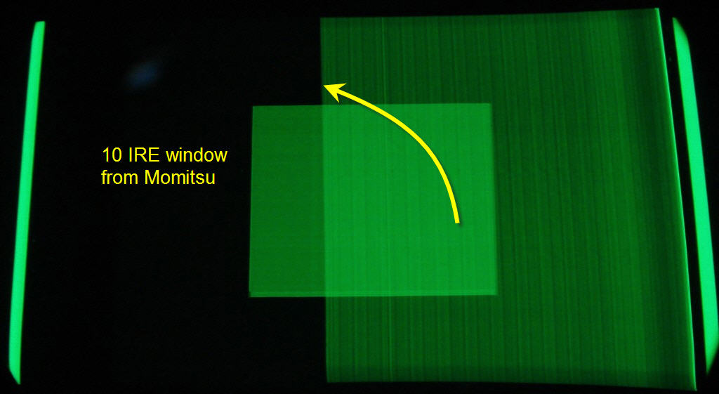
I've noticed some strange things (raster artifacts?) on my 8500. It's only noticeable at very low IREs. The attached pix (taken through the green lens) show what it looks like.
8500raster.jpg is a 10IRE window from Avia. Notice the "curtain" of noise or whatever on the right side. It almost looks like a folded raster, except the part that looks like a "raster fold-under" (on the right side) is actually not the edge of the raster. The bars on the sides are a "border" that my @#%# Momitsu DVD player displays around the active image area (porches?), and I've never been able to get rid of it. So the edge of the raster is outside those bars. Possible clue: although it doesn't show in this pic, the left edge of the noise is exactly lined up with the "Christie dot."
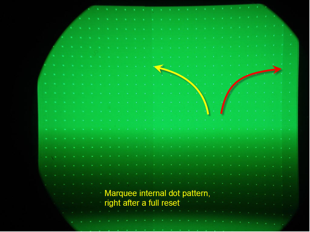
I saw an odd "rectangle of video noise" on another 8500 that (I think) turned out to be my Momitsu. So I turned off the Momitsu, did a full reset on the 8500, and maxed the Brightness setting. I could just see the left side of the noise in the internal dot pattern (8500raster2.jpg). The right side (red arrow) is different than what I saw on the Momi screen, but it shouldn't be there at all. The left side (yellow arrow) is in exactly the same spot as in the first picture.
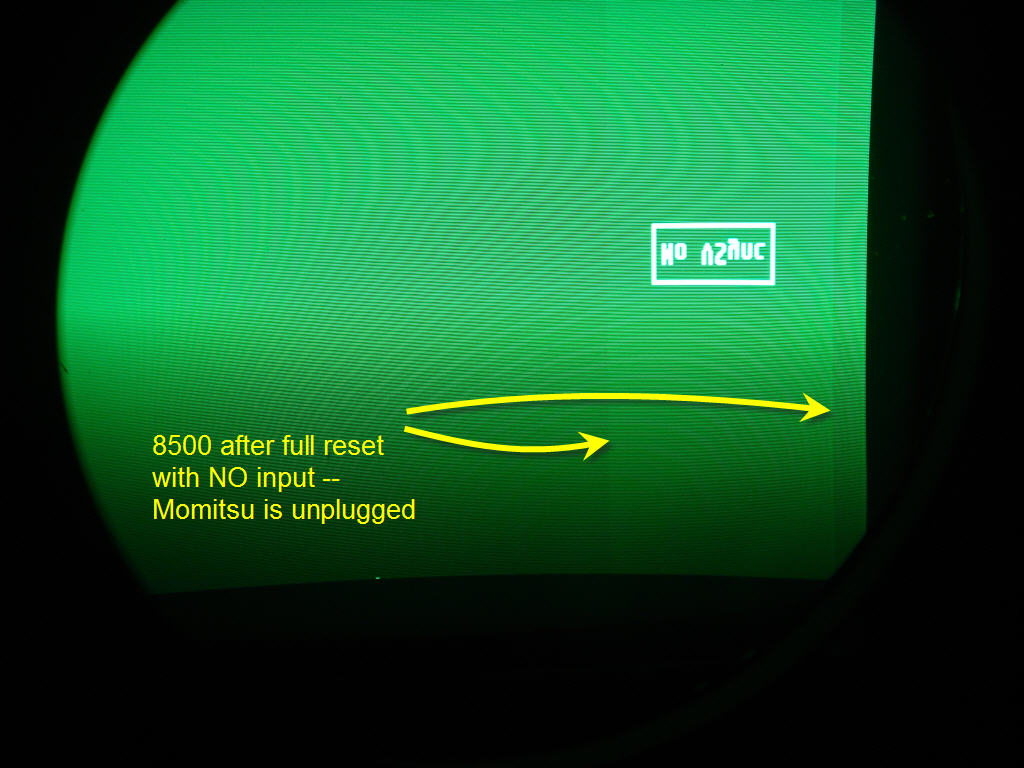
So then just to be sure (since the Momi puts out a sync signal even when it's turned off), I completely unplugged the DVD player from the 8500's inputs, and turned it on again. Now the noise is in a different place (due to different scan rates maybe?) but it's still there -- 8500raster3.jpg.
I tried pulling the contrast modulation (color correction) board, and that didn't change it.
Any guesses?
Thanks!
Gary
| Description: |
|
| Filesize: |
57.66 KB |
| Viewed: |
12739 Time(s) |
|
| Description: |
|
| Filesize: |
79.34 KB |
| Viewed: |
12738 Time(s) |
|
| Description: |
|
| Filesize: |
113.71 KB |
| Viewed: |
12738 Time(s) |
|
|
|
| Back to top |
|
 |
tse
Joined: 03 May 2006
Posts: 1014
Location: Sweatbucket, Fl.
|
| Posted: Sat May 12, 2007 11:44 pm Post subject: |
|
|
That looks like the residue from the video clamp pulse that is sent to the neck cards during horizontal retrace. Can you see it on the screen?
Scott
_________________
"Were we directed from Washington when to sow and when to reap, we would soon want bread."
Thomas Jefferson
|
|
| Back to top |
|
|
garyfritz
Joined: 08 Apr 2006
Posts: 12088
Location: Fort Collins, CO
|
| Posted: Sun May 13, 2007 3:00 pm Post subject: |
|
|
|
Just barely, in near-total blackouts. The Avia picture is misleading -- it's actually about 5 IRE, not 10. But I'd like to get rid of it if I could. Any suggestions?
|
|
| Back to top |
|
|
tse
Joined: 03 May 2006
Posts: 1014
Location: Sweatbucket, Fl.
|
| Posted: Sun May 13, 2007 4:37 pm Post subject: |
|
|
There is a VDC ECO that involves installing three 1.5M (I think) resistors on the VIM. Will try to dig up more info tomorrow.
Scott
_________________
"Were we directed from Washington when to sow and when to reap, we would soon want bread."
Thomas Jefferson
|
|
| Back to top |
|
|
draganm

Joined: 08 Mar 2006
Posts: 8990
Location: Colorado
|
| Posted: Sun May 13, 2007 5:52 pm Post subject: |
|
|
| tse wrote: | There is a VDC ECO that involves installing three 1.5M (I think) resistors on the VIM. Will try to dig up more info tomorrow.
Scott |
I would be interested in that as well. The list of ECO's on this web-site only covers up to early 2000 I think, If you and Kal could add a few more current ones that would be great.
|
|
| Back to top |
|
|
tse
Joined: 03 May 2006
Posts: 1014
Location: Sweatbucket, Fl.
|
| Posted: Mon May 14, 2007 11:35 pm Post subject: |
|
|
The resistor positions were changed to the component side of the bd in later builds. They got in the way of the ATE and ICT equipment. Placement isn't critical but best to have resistors close to the opamp inputs.
Scott
| Description: |
|

Download |
| Filename: |
PhntLine.zip |
| Filesize: |
257.33 KB |
| Downloaded: |
375 Time(s) |
_________________
"Were we directed from Washington when to sow and when to reap, we would soon want bread."
Thomas Jefferson
|
|
| Back to top |
|
|
garyfritz
Joined: 08 Apr 2006
Posts: 12088
Location: Fort Collins, CO
|
| Posted: Tue May 15, 2007 4:17 am Post subject: |
|
|
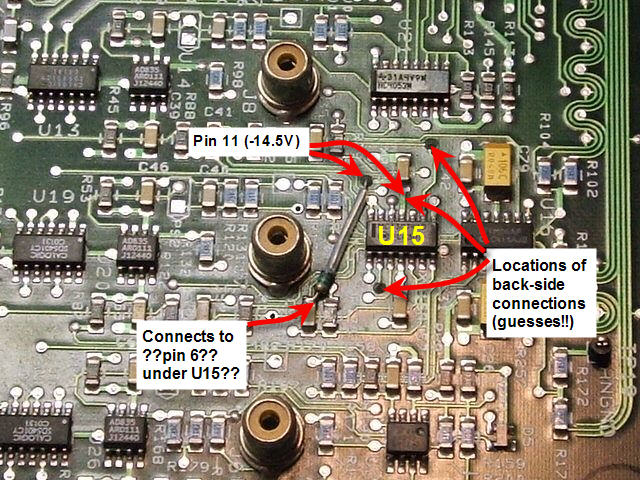
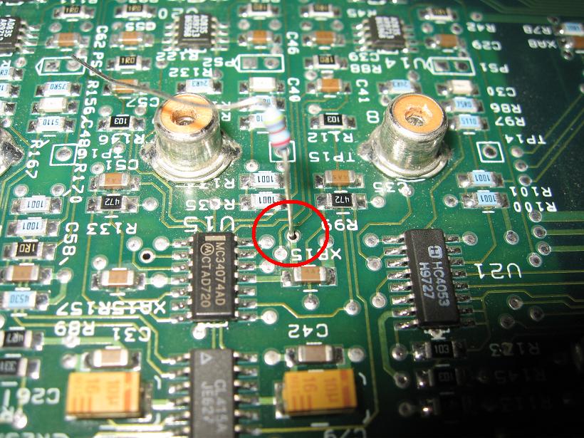
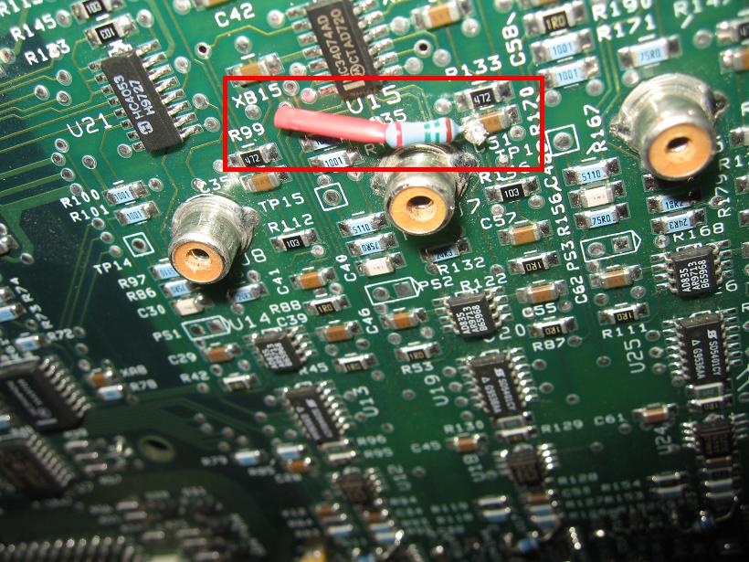
Hm. I'd have to compare the board to the pix to see exactly what to do, but it should be do-able. Hard to tell what's what from the pix. From the schematic it looks like you run the resistors from pins 2, 6, and 9 of U15 to -14.5V, which is handily available at pin 11 of U15. U15 seems to be the one just to the right of the component-side resistor. Putting the resistors all on the component side would be tricky -- pin 11 would get a mite crowded.
Would you check my picture and see if I've got it right so far?
I'm not sure this is the same problem, though. They describe it as a faint vertical line, not a rectangular area taking up a good part of the screen. Do you think it could be the same issue, Scott?
I occasionally see a faint vertical line on the LEFT side of the screen, but I'm not sure if that's coming from the projector or not.
| Description: |
|
| Filesize: |
118.69 KB |
| Viewed: |
12612 Time(s) |
|
|
|
| Back to top |
|
|
CZ Eddie
Joined: 23 Mar 2006
Posts: 1601
Location: Austin, TX
|
| Posted: Tue May 15, 2007 11:51 am Post subject: |
|
|
Gary's pic:

I've got the same thing on mine. I knew it was a bulletin fix but never got around to finding the bulletin and fixing it. Maybe now it's time. 
_________________
Back after a digital sabatical.
|
|
| Back to top |
|
|
tse
Joined: 03 May 2006
Posts: 1014
Location: Sweatbucket, Fl.
|
| Posted: Tue May 15, 2007 10:56 pm Post subject: |
|
|
Gary,
Your pic looks right. The line described in the ECO happens on the edge of the darker area after the video peaking mod is installed. I'm pretty sure that this change will lessen or eliminate the dark bar.
Scott
_________________
"Were we directed from Washington when to sow and when to reap, we would soon want bread."
Thomas Jefferson
|
|
| Back to top |
|
|
garyfritz
Joined: 08 Apr 2006
Posts: 12088
Location: Fort Collins, CO
|
| Posted: Thu May 17, 2007 10:51 pm Post subject: |
|
|
Hey, it turns out this ECO is on Curt's site already: http://www.curtpalme.com/docs/ElectrohomeMarqueeTechnicalBulletin_LineFix.pdf
Putting those two resistors on the back sure looks a lot easier. Scott, I'm not even sure what ATE and ICT equipment is but I don't think I have any.  There's no reason I have to put all 3 resistors on the component side, is there? There's no reason I have to put all 3 resistors on the component side, is there?
|
|
| Back to top |
|
|
tse
Joined: 03 May 2006
Posts: 1014
Location: Sweatbucket, Fl.
|
| Posted: Fri May 18, 2007 12:08 am Post subject: |
|
|
That's pretty cool that it is already available. I searched on VDCDS's site and didn't see it there. I figured that it wasn't public.
It's perfectly fine to locate the parts on either or both sides. The original ECO had them as shown on the FSB. The board assy manufacturer requested them moved to the component side so they wouldn't interfere with their automated test equip and in circuit testing.
Scott
_________________
"Were we directed from Washington when to sow and when to reap, we would soon want bread."
Thomas Jefferson
|
|
| Back to top |
|
|
draganm
Joined: 08 Mar 2006
Posts: 8990
Location: Colorado
|
| Posted: Fri May 18, 2007 12:33 am Post subject: |
|
|
that's one of the mods I've never done, looks like a real PITA 
|
|
| Back to top |
|
|
garyfritz
Joined: 08 Apr 2006
Posts: 12088
Location: Fort Collins, CO
|
| Posted: Fri May 18, 2007 3:46 am Post subject: |
|
|
Eh, if you put the two resistors on the back, it doesn't look any worse than the LVPS P14 mod. No trace cutting, no soldering surface-mount resistors down in a hole, just add on a few resistors.
I'm glad you posted yours anyway, Scott. Your post has better pictures and includes the schematic, which is nice.
|
|
| Back to top |
|
|
garyfritz
Joined: 08 Apr 2006
Posts: 12088
Location: Fort Collins, CO
|
| Posted: Mon May 21, 2007 4:06 am Post subject: |
|
|
Scott, before I tackle that ECO: take a look at the attached pic. I used the blue this time because it was more visible than the green.
Notice on the attached pic, the "noise box" is not just a brighter area on the raster. You can see that the box is almost like an EXTRA raster. I lost all my convergence settings when we cleaned the chips on my CLM, so the blue raster has some pincushion on it. But the "noise box" has a flat bottom, and its bottom sticks out below the bottom of the "real" raster!!
That's not the kind of thing the ECO is addressing, is it?
This is really not a fatal problem. I didn't even notice it until I realized I had the brightness set a few clicks too high on my **DVD player**. That elevated the black level coming out of the player and washed out the noise box. (And we just took a look at Dragan's pj yesterday, and noticed similar noise when we lowered the brightness on his TheaterTek player. So it may be a common problem?)
So if I had to, I have an easy way to make it go away. But I think I'd lose some deep shadow detail in the process and I'd rather not do that. I'd really rather get rid of this "extra raster." Any suggestions?
Thanks!!
Gary
| Description: |
|
| Filesize: |
65.08 KB |
| Viewed: |
12486 Time(s) |
|
|
|
| Back to top |
|
|
CZ Eddie
Joined: 23 Mar 2006
Posts: 1601
Location: Austin, TX
|
| Posted: Mon May 21, 2007 4:21 am Post subject: |
|
|
I've seen the issue mentioned in this bulletin posted above. It's definately *not* the issue you have started this thread about. 
_________________
Back after a digital sabatical.
|
|
| Back to top |
|
|
CZ Eddie
Joined: 23 Mar 2006
Posts: 1601
Location: Austin, TX
|
| Posted: Mon May 21, 2007 4:30 am Post subject: |
|
|
Gary, what year was your 8500 built in? This issue is something that I didn't see on older Marquee's and have only seen it on newer ones I think.
I just looked through the newer TB's that Curt has posted and I think he's missing a few. I'll check my X-Files sometime this week to see if I can come up with any more TB's. Hopefully one of them will address this raster byproduct we are both seeing. Btw, my 9500 was built in December of 2000 and has a non-original 03P VIM.
_________________
Back after a digital sabatical.
|
|
| Back to top |
|
|
garyfritz
Joined: 08 Apr 2006
Posts: 12088
Location: Fort Collins, CO
|
| Posted: Mon May 21, 2007 4:41 am Post subject: |
|
|
Eureka!! I suddenly had a flash of insight.
My Momitsu DVD player has always displayed this "border" around the image area. It's like the porches were lit up at about IRE 10 or so. I've never been able to figure out how to make them go away. They were even visible if I hooked the Momitsu up to a CRT monitor.
When I thought about what I said about the DVD player brightness, I thought, hmmmm... I just tried RAISING the DVD player brightness level up to the point where a maximum-black (digital level 0, blacker than black) background **matched** the border. If I'd done that on a CRT monitor, I think the whole display would have been washed out. But my projector has more control over brightness! So I cranked the Marquee's brightness waaay down, and... NO BOX! I'm sure it's still there, but with the brightness so low it's invisible. You can't even see a box looking into the tube, even if the brightness is high enough to see a 0% stim (digital level 16) box on a maximum black (digital level 0) background. So I don't have to worry about losing shadow detail, I've gotten rid of the noise boxes, AND I've finally gotten rid of the damn Momitsu's border.
Three YEARS I've had this player, and I finally figure out whatinhell it's doing...  It seems bloody obvious in retrospect, but I was always looking in the wrong place. Wish I'd figured this out when I had my XG!! I always had raster artifact problems with that too, and I think this higher-player-brightness change would have solved that too. I will be very interested to see what the PQ is like once I get this dialed in again. It seems bloody obvious in retrospect, but I was always looking in the wrong place. Wish I'd figured this out when I had my XG!! I always had raster artifact problems with that too, and I think this higher-player-brightness change would have solved that too. I will be very interested to see what the PQ is like once I get this dialed in again.
Of course, now I **DO** see the vertical line mentioned in the ECO. But so far I haven't seen it on the screen. If I notice it once I get this properly set up again, I'll know how to fix it.
With the player brightness set high enough to do this, the Marquee's brightness is down around 32 !! But that seems to be the right level to match with the signal the Momitsu is putting out. We'll see if it continues to make sense as I set this up.
EDIT: Eddie, my 8500 was built Jan 96.
Gary
|
|
| Back to top |
|
|
CZ Eddie
Joined: 23 Mar 2006
Posts: 1601
Location: Austin, TX
|
| Posted: Mon May 21, 2007 5:01 am Post subject: |
|
|
Congrats, Gary.
Btw I checked the x-files and I don't have any bulletin's that address this anomaly.
I did notice while poking around though, that I've put on almost exactly 1000 hours in almost exactly six months.
_________________
Back after a digital sabatical.
|
|
| Back to top |
|
|
CZ Eddie
Joined: 23 Mar 2006
Posts: 1601
Location: Austin, TX
|
| Posted: Tue Jul 17, 2007 11:28 pm Post subject: |
|
|
FYI: The TB95-10 for "Folded Image" didn't do anything for me. I just performed that mod (very easy to do, one diode only) and didn't notice any difference.
Also, we can rule out the VIM & VNB's because I removed mine and put some older 8500 boards in mine. And I still have the same artifact shown in your pics above.
I was sure it was the Folded Image TB because thats almost what it looks like. So now I'm going to see if I can find the parts for the Line Mod to see if that does it afterall.
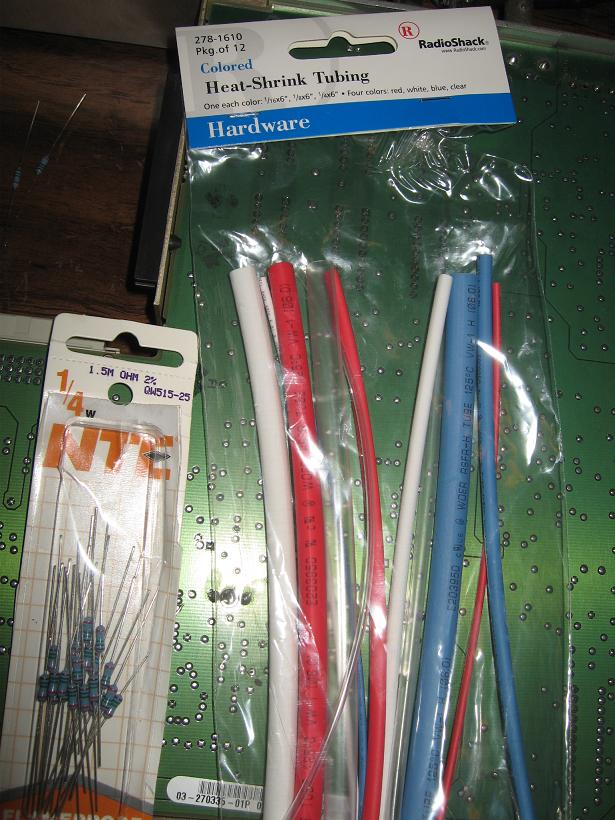
Edit. I do have the parts, but it calls for 1.5M 1/8 watt and I only have 1.5M 1/4 watt. So I'll try these out. I'll use shrink tubing to get it done.
_________________
Back after a digital sabatical.
|
|
| Back to top |
|
|
CZ Eddie
Joined: 23 Mar 2006
Posts: 1601
Location: Austin, TX
|
| Posted: Wed Jul 18, 2007 12:59 am Post subject: |
|
|
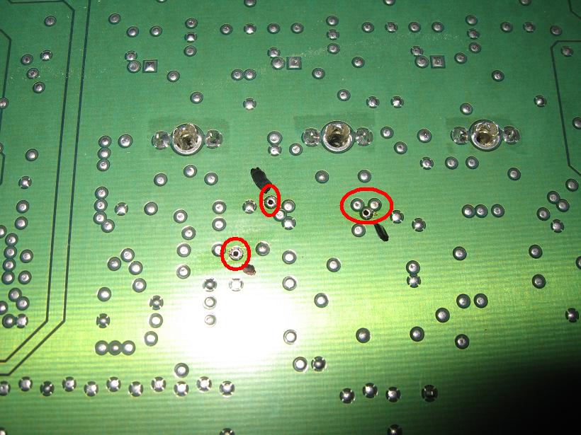
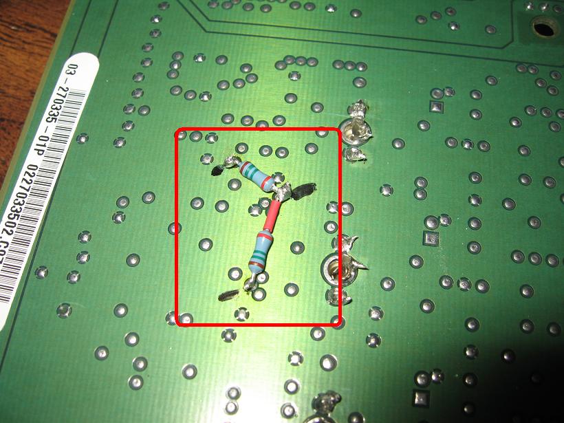
Gary, good news!!
The artifact is not "gone", but it is drastically reduced!! I can really only notice it if I set my brightness "too high".
And the line is 95% gone also!
Perhaps it might have all gone away 100% (not likely) if I were a better solderer, or if I'd been able to locate the solder I'm using to working with. The stuff I'm using today (ratshack .052 60/40) doesn't work that great. It's kind of "runny". Which is good for filling in holes but it also goes everywhere else!!!!
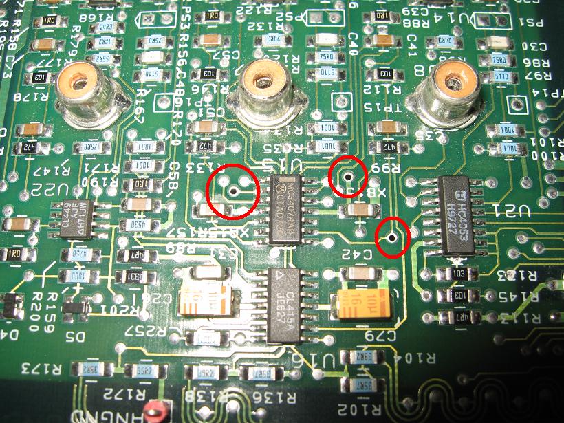
Don't worry about the black marks you see in the picture. That was me marking my spots with a black permanent ink marker.
All the parts in the first pic are what I needed. I pulled the resistors out of an old stash I picked up at Fry's. The tubing came from Radio Shack. I'm sure either place has both items. Though Fry's would be my first stop due to Ratshack pulling out of the bitty components business these days.
| Description: |
|
| Filesize: |
101.81 KB |
| Viewed: |
12361 Time(s) |
|
| Description: |
|
| Filesize: |
127.43 KB |
| Viewed: |
12359 Time(s) |
|
| Description: |
|
| Filesize: |
156.35 KB |
| Viewed: |
12359 Time(s) |
|
| Description: |
|
| Filesize: |
92.01 KB |
| Viewed: |
12359 Time(s) |
|
| Description: |
|
| Filesize: |
129.28 KB |
| Viewed: |
12359 Time(s) |
|
| Description: |
|
| Filesize: |
90.65 KB |
| Viewed: |
12359 Time(s) |
|
_________________
Back after a digital sabatical.
|
|
| Back to top |
|
|
|
|


