| Author |
Message |
AFryia

Joined: 09 Mar 2006
Posts: 965
Location: S.E. Michigan VPH-G70Q
|
| Posted: Thu Aug 22, 2024 12:24 am Post subject: |
|
|
| kal wrote: | | station_equation wrote: | | The raster size set in the registration steps is the maximum size the machine will ever project? The separate size adjustment based on input source has me wondering that if I max the default registration size, a specific input would then overdrive that. |
Yes - Raster is the max area the active image may occupy. The raster is not (normally) seen on the screen. It's normal to have the raster to be a bit larger than the actual active image area because when the electron gun swings back to the start side you want some "time" for it to stabilize before it starts painting.
It's not uncommon to set the RASTER to be larger than the tube surface and use blanking to blank out left/right/top/bottom to ensure that you don't by accident move the IMAGE that is within the RASTER off the tube face.
| station_equation wrote: | | Also, the ratio of the horizontal and vertical 0-255 values isnt a 4:3 ratio. How do you ensure that you arent squeezing/stretching? |
Set the width in the tubes as you'll always run out of width before height. Then project and measure on screen to ensure you've got the ratio you want.
Kal |
Like riding a bike isn't it! 
_________________
My Volt Blog
|
|
| Back to top |
|
 |
kal
Forum Administrator
Joined: 06 Mar 2006
Posts: 18114
Location: Ottawa, Canada
TV/Projector: JVC DLA-NZ7
|
|
| Back to top |
|
|
ElTopo
Joined: 07 Nov 2006
Posts: 1640
|
| Posted: Thu Aug 22, 2024 10:36 am Post subject: |
|
|
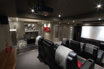
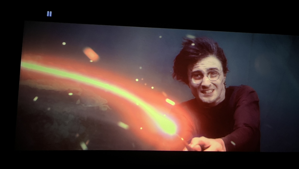
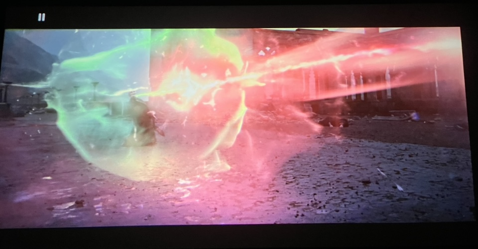
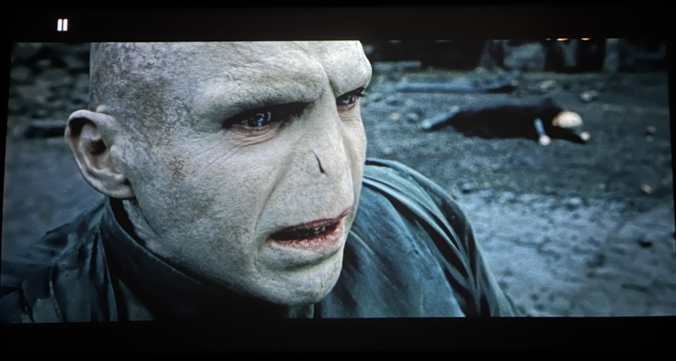
Some shots from Harry Potter 4K on my Marquee from Oppo203. Downscaled to 1080p and Tone Mapping done by the Oppo.
Screen has 3,3m in width 16:9
| Description: |
|
| Filesize: |
270.22 KB |
| Viewed: |
1180 Time(s) |
|
| Description: |
|
| Filesize: |
117.6 KB |
| Viewed: |
1180 Time(s) |
|
| Description: |
|
| Filesize: |
124.95 KB |
| Viewed: |
1180 Time(s) |
|
_________________
Barco Cine 9 the one and only
|
|
| Back to top |
|
|
station_equation
Joined: 04 Aug 2024
Posts: 32
Location: Peoria, IL
|
| Posted: Sat Aug 24, 2024 2:32 pm Post subject: |
|
|
Sorry for the incredibly basic questions, but the margins seem pretty slim here with parts being unavailable, I don't want to blow anything up.
But, looking into the lens, there's a single horizontal line at the bottom (so top of projected screen) of all 3 tubes. THAT is supposed to be adjusted off of the tube face, correct, and it's okay to do so without concern about electrons hitting off the phosphor face? Its not vertical foldover?
_________________
Jeremy
Sony G90 / Pioneer HLD-X9 / Radiance 2144 / Marantz SR5011
|
|
| Back to top |
|
|
kal
Forum Administrator
Joined: 06 Mar 2006
Posts: 18114
Location: Ottawa, Canada
TV/Projector: JVC DLA-NZ7
|
|
| Back to top |
|
|
station_equation
Joined: 04 Aug 2024
Posts: 32
Location: Peoria, IL
|
| Posted: Sun Aug 25, 2024 12:35 am Post subject: |
|
|
Perfect! Ill stop worrying about it then. It was a small concern after a bigger one had me doubting the whole affair. I was getting an inconsistent code 71 (Green tube overcurrent), which was really making me nervous.
During this exercise I learned that the person who renovated my house put 3-prong outlets on ungrounded circuits, and without a ground there was 40V AC on the G90s chassis. Which I learned the hard way with a healthy shock when putting the case pieces back on.
I pulled a new circuit to get something grounded to that part of the house, and it seems like the 71s have stopped.
_________________
Jeremy
Sony G90 / Pioneer HLD-X9 / Radiance 2144 / Marantz SR5011
|
|
| Back to top |
|
|
kal
Forum Administrator
Joined: 06 Mar 2006
Posts: 18114
Location: Ottawa, Canada
TV/Projector: JVC DLA-NZ7
|
|
| Back to top |
|
|
nin
Joined: 01 Mar 2012
Posts: 33
|
| Posted: Wed Sep 04, 2024 8:59 pm Post subject: |
|
|
| kal wrote: |
While following the manual for throw distance is always a good bet (and is usually recommended for new users), to maximize tube life even further do the following steps:
1. Put the projector on the cart or simply leave it on the floor so that you can move it.
2. Display something that fills the screen entirely (like a grid test pattern).
3. Using only the green (middle) tube, look into the tube and increase the image width on the tube face until it is around 1/8" to 1/4" from the edge of the white phosphor. Under no circumstances should you allow the image to go off of the white phosphor surface!
4. Move the projector back and forth until the image fits your screen.
5. THAT is the correct throw distance for optimal phosphor usage.
It'll usually be 5-8% closer than what the manual tell you because the manual throw instructions are conservative since they make you install blindly without even looking in the tubes at all.
You then toe (angle) in the other two lenses to fit. |
Hope it is ok to ask this here. I have a D50 and will set it up this weekend. I will have it on the floor inside a table. I wonder how much "tilt" is ok? The room is so that my screen need to be 50 cm (19 inches) up from the floor. Any problem to have the D50 just 10 inches up from the floor and tilted up?
|
|
| Back to top |
|
|
kal
Forum Administrator
Joined: 06 Mar 2006
Posts: 18114
Location: Ottawa, Canada
TV/Projector: JVC DLA-NZ7
|
| Posted: Wed Sep 04, 2024 9:27 pm Post subject: |
|
|
| nin wrote: | | Hope it is ok to ask this here. I have a D50 and will set it up this weekend. I will have it on the floor inside a table. I wonder how much "tilt" is ok? The room is so that my screen need to be 50 cm (19 inches) up from the floor. Any problem to have the D50 just 10 inches up from the floor and tilted up? |
The more square you keep the image on the tube face the better as you can maximize tube face usage.
So ideal for any CRT projector (not just the D50) is off the floor half way up the screen and tilted so that the tube face surface is parallel with the screen as that way you have an actual rectangle on the tube face instead of a trapezoid. Of course nobody does this as it's a really annoying installation spot as it eats up the best seat in the house and blocks any sightlines from behind. So most people ceiling mount, and the lower you can get it, the better, to make the image area on the tubes as square as possible so that you can make it as wide as possible to use as much phosphor as possible. Some people will do the exact same but with a floor mount, but that eats up the best seat in the house.
In your case I have no idea how that 10" off the floor and tilted an unknown amount translates to "optimal". Try it and see what you see on the tube face.
Kal
_________________

Support our site by using our affiliate links. We thank you!
My basement/HT/bar/brewery build 2.0
Last edited by kal on Thu Sep 12, 2024 5:26 pm; edited 2 times in total
|
|
| Back to top |
|
|
nin
Joined: 01 Mar 2012
Posts: 33
|
| Posted: Wed Sep 04, 2024 9:34 pm Post subject: |
|
|
|
Thanks, I will test it this weekend.
|
|
| Back to top |
|
|
station_equation
Joined: 04 Aug 2024
Posts: 32
Location: Peoria, IL
|
| Posted: Tue Sep 10, 2024 1:51 am Post subject: Flickering Text |
|
|
The fun never stops!
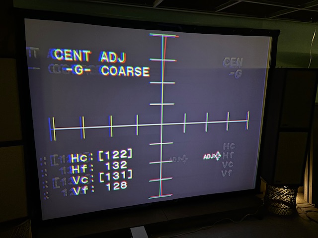
The text used to be solid as a rock. A couple of evenings ago I was running a long calibration session and the on-screen text started to jitter. Was fine the next day, and now its jittery again right on power up. Test patterns are solid, input image is good. Its just on-screen text.
Bad caps somewhere? Off-brand Dallas from the seller, who says it was replaced before shipping? YA board troublemaker is from a good lot and no LCD warnings.
| Description: |
|
| Filesize: |
81.92 KB |
| Viewed: |
950 Time(s) |
|
_________________
Jeremy
Sony G90 / Pioneer HLD-X9 / Radiance 2144 / Marantz SR5011
|
|
| Back to top |
|
|
HaydnG90

Joined: 22 May 2006
Posts: 1356
|
| Posted: Tue Sep 10, 2024 6:02 pm Post subject: |
|
|
|
Where are your calibration settings? You should do a mechanical setup with adjustments at midpoint, then use the electronics to fine tune convergence etc. There are known counterfeit Dallas chips on Ebay. They usually have a far shorter lifespan than the real thing eg 5years vs 10 years. Ask FH where they sourced it.
|
|
| Back to top |
|
|
ElTopo
Joined: 07 Nov 2006
Posts: 1640
|
| Posted: Thu Sep 12, 2024 9:10 am Post subject: Re: Flickering Text |
|
|
Would be nice to see when the G90 is running finally calibrated (mechanically, convergence,....)
_________________
Barco Cine 9 the one and only
|
|
| Back to top |
|
|
Curt Palme
CRT Tech
Joined: 08 Mar 2006
Posts: 24396
Location: Langley, BC
TV/Projector: All of them!
|
| Posted: Fri Sep 13, 2024 7:27 pm Post subject: |
|
|
IT's a bad YA board. I've seen that problem here a few times, and had Craig Rounds repair a few of them.
Craig seems to have disappeared for some reason. He hasn't returned my last 2 emails. I just found his number, I'll call him later today.
|
|
| Back to top |
|
|
station_equation
Joined: 04 Aug 2024
Posts: 32
Location: Peoria, IL
|
| Posted: Fri Sep 13, 2024 10:01 pm Post subject: |
|
|
| Curt Palme wrote: | IT's a bad YA board. I've seen that problem here a few times, and had Craig Rounds repair a few of them.
Craig seems to have disappeared for some reason. He hasn't returned my last 2 emails. I just found his number, I'll call him later today. |
Did he happen to say which part of it goes bad? I have zero microsoldering skills, so I won't be replacing anything on my own, but just curious about how they get to this point when thinking about trying to source replacements.
Though, I have an email into FH about it as well. We'll see if they cough up another board from one of the leftovers, but who knows how many dozens of hours that will last.
_________________
Jeremy
Sony G90 / Pioneer HLD-X9 / Radiance 2144 / Marantz SR5011
|
|
| Back to top |
|
|
Tim in Phoenix

Joined: 21 Oct 2006
Posts: 4409
Location: Phoenix
|
| Posted: Sat Sep 14, 2024 4:36 am Post subject: |
|
|
Guys
Curious if the glycol in the tubes has turned to black jello by now.......?
|
|
| Back to top |
|
|
kal
Forum Administrator
Joined: 06 Mar 2006
Posts: 18114
Location: Ottawa, Canada
TV/Projector: JVC DLA-NZ7
|
|
| Back to top |
|
|
Curt Palme
CRT Tech
Joined: 08 Mar 2006
Posts: 24396
Location: Langley, BC
TV/Projector: All of them!
|
| Posted: Sat Sep 14, 2024 9:46 pm Post subject: |
|
|
| station_equation wrote: | | Curt Palme wrote: | IT's a bad YA board. I've seen that problem here a few times, and had Craig Rounds repair a few of them.
Craig seems to have disappeared for some reason. He hasn't returned my last 2 emails. I just found his number, I'll call him later today. |
Did he happen to say which part of it goes bad? I have zero microsoldering skills, so I won't be replacing anything on my own, but just curious about how they get to this point when thinking about trying to source replacements.
Though, I have an email into FH about it as well. We'll see if they cough up another board from one of the leftovers, but who knows how many dozens of hours that will last. |
No, he doesn't give the secrets away as to how he makes his living. Neither do I. 
Last I heard, he charges about $1000 US to fix a YA board. Back when the sets were still worth $6-10K, that was a bargain, but the labor needed to repair these hasn't gotten any less, despite the value of a G90 now.
|
|
| Back to top |
|
|
Curt Palme
CRT Tech
Joined: 08 Mar 2006
Posts: 24396
Location: Langley, BC
TV/Projector: All of them!
|
| Posted: Sat Sep 14, 2024 9:48 pm Post subject: |
|
|
Craig's eBay ad. (he will probably give a bit of a discount if you buy directly)
https://ebay.us/QLKVew
|
|
| Back to top |
|
|
HaydnG90
Joined: 22 May 2006
Posts: 1356
|
| Posted: Sun Sep 15, 2024 6:53 am Post subject: |
|
|
|
Let us know how FH respond. This has to be a warranty issue given how quickly the problem developed.
|
|
| Back to top |
|
|
|
|


