|
As this forum is rarely used anymore, we've locked it. Feel free to browse and read. Questions? Please reach out to us directly. Cheers! |

|
 |
|
|
| Author |
Message |
Lee2023
Joined: 30 Apr 2023
Posts: 18
|
| Posted: Tue Jul 30, 2024 12:30 am Post subject: Repotting QUAD Multiplier Runco 940 / Barco 70X |
|
|
Hi !
I have been giving a really nice Runco DTV-940, phosphor is like new, image as sharp as this projector can be, i'm really happy,
But...... i have unstable raster size in changing and a bit brightness with peak discharge, first start I had HV clics....
So the quadrupler was arcing, cleaned a bit and removed the bracket and isolated the local spot with kapton to test things, no more arcs, but I can hear some faint bzittt that coincide with raster reduction vertical and horizontal, so I will remove all the silicon and do a repotting, anyway silicon is so brittle from age and heat, should be easy
I need advise since I have no experience with repotting HV circuits, was should I use after cleaning everything ?? Don't want to use the bad product and have the risk of messing up components from bad HV isolation
Help WILL be appreciated since it's my chance to have a really good shape projector finally !!!
Thanks,
Lee
|
|
| Back to top |
|
 |
Curt Palme
CRT Tech
Joined: 08 Mar 2006
Posts: 24396
Location: Langley, BC
TV/Projector: All of them!
|
| Posted: Tue Jul 30, 2024 3:34 am Post subject: |
|
|
Don't even try it. A bunch of people (well, a few) tried doing it about 15 years ago, and only one worked.. for 1/2 hour. Then it blew up violently.
A shaking image is usually a bad splitter, not a bad quad.
|
|
| Back to top |
|
|
Lee2023
Joined: 30 Apr 2023
Posts: 18
|
| Posted: Tue Jul 30, 2024 4:15 am Post subject: |
|
|
Ok but the edge of the quad near the bracket, plastic is all turned to carbon, arcing... so inside I supposed it doesn't look good, I have reduction of vertical and horizontal size of the raster synced, like zooming, and all 3 tubes with the same effect, lower HV implied lower electron speed and more time for deflection in boot direction, so increase of the raster size in both direction normally, please explain why a bad splitter will do this more than the quad, since the HV problem can be the quad or the splitter... and the quad is arcing so bad dielectric stuff in there
Crazy question, how about redoing the enclosure and using oil ? Some HV charging caps supplies for laser flash lamps have all their HV ladder in an enclosure with oil...
How about doing something more bigger with a lot of space within the HV ladder on the side of the projector, really big gaps then potting this, ?? the problem is this is really compact and not easy for DIY people to have the right potting stuff and people want to have a repair like the original projector, and they wanted to crowd everything in there.... so why not make this bigger to have a really good margin, should work ?
I will not name the cie XXXXX is doing HV supplies with same thing, I have design supplies with the same concept, Xformer boost output and voltage multiplier, my stuff was 6-8 kV but it's the same thing, make the gap bigger, the caps have more kV and it should work
Let me know,
Thanks,
|
|
| Back to top |
|
|
Lee2023
Joined: 30 Apr 2023
Posts: 18
|
| Posted: Tue Jul 30, 2024 4:35 am Post subject: |
|
|
How much caps in there 34.5/8 approx 5kV per cap, should be possible to buy ceramics from digikey and redesign this thing
Question is HV start at the same time as the filament supply, so normally current is lower and the HV will be higher at startup, since the supply will be not really loaded, same thing in some tubes amplifiers.. ? The splitter doesn't normally contain any bleeding resistors ? so there must be a peak HV at startup then with increase of current going to 34.5kV ? Need to chose caps with a higher voltage rating... 3nF caps I have seen to be in there
https://www.digikey.ca/en/products/detail/calramic-technologies-llc/D100D135CR17302KR/20526416
Problem with this is the way it's build, lead are really near for 10 kV so axial is better or more path,
https://www.digikey.ca/en/products/detail/tdk-corporation/FHV-2AN/716643
But this x8 is a 800$ project so mmm maybe surplus store...
Other caps in // with higher voltage rating have sometime physical size that complicate things
Solution is I think find a deal in a surplus store with ceramic cap for transmitter stuff 3nF in one cap and doing a really big Frankenstein thing on the size that will last forever... I will not let this thing die, tubes are to good
Last edited by Lee2023 on Tue Jul 30, 2024 4:57 am; edited 6 times in total
|
|
| Back to top |
|
|
Lee2023
Joined: 30 Apr 2023
Posts: 18
|
| Posted: Tue Jul 30, 2024 4:47 am Post subject: |
|
|
Is there a way to remove the HV G2 lead from the G2 divider ? I don't want to cut the wire and redo an HV junction after...
Thanks !!!
|
|
| Back to top |
|
|
Lee2023
Joined: 30 Apr 2023
Posts: 18
|
| Posted: Tue Jul 30, 2024 4:54 am Post subject: |
|
|
|
Okkk HV supply is regulated via a divider at the splitter.... so normally no HV overshoot at startup, learning... but this doesn't eliminate the possibility that the HV variation can be the quad of the splitter ?
|
|
| Back to top |
|
|
Lee2023
Joined: 30 Apr 2023
Posts: 18
|
| Posted: Tue Jul 30, 2024 3:24 pm Post subject: |
|
|
Hi,
Soo after sleeping on this,
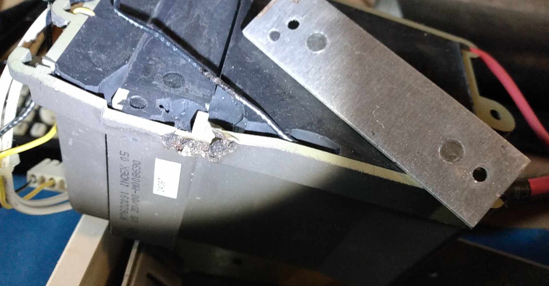
Carefully look at the direction of the possible arcing on the edge of the alu bracket... it's seems to be not from the inside, the damage is purely external,
So nothing on top of that with HV just the frame, so it can't come from the top
The inspection of the inside of the quad, along the side of the plastic enclosure reveal no burning marks witch I think would be impossible if arcing was from the inside to the outside, it's perfectly clean, and the damage melting would have been form the inside to the bracket...
The shape of the destruction seems to indicate arcing between the black HT return and the frame, but the wire is not melted, partially attacked like in the way of the arcing... so my guess is a bad return to the board ?? and arcing between the return wire and the edge of the bracket since this wire if the HT return is bad must go to some HV potential... but the path of less potential should have been at the connector anyway, and the insulation would have melt
Cleaned everything this morning and raster is stable, so mmm mmm not sure what is going on here, ever saw that ??
Thanks !!
| Description: |
|

Download |
| Filename: |
452820545_958008486080646_5092128317457939717_n.jpg |
| Filesize: |
95.25 KB |
| Downloaded: |
56 Time(s) |
|
|
| Back to top |
|
|
Lee2023
Joined: 30 Apr 2023
Posts: 18
|
| Posted: Tue Jul 30, 2024 3:24 pm Post subject: |
|
|
002
| Description: |
|
Download |
| Filename: |
452541852_1281619419467759_1499829598922697265_n.jpg |
| Filesize: |
81.15 KB |
| Downloaded: |
67 Time(s) |
|
|
| Back to top |
|
|
Lee2023
Joined: 30 Apr 2023
Posts: 18
|
| Posted: Tue Jul 30, 2024 3:25 pm Post subject: |
|
|
003
| Description: |
|
Download |
| Filename: |
452843462_3795889927309072_2400272879275072195_n.jpg |
| Filesize: |
125.88 KB |
| Downloaded: |
61 Time(s) |
|
|
| Back to top |
|
|
Lee2023
Joined: 30 Apr 2023
Posts: 18
|
| Posted: Tue Jul 30, 2024 3:27 pm Post subject: |
|
|
004
| Description: |
|
| Filesize: |
105.33 KB |
| Viewed: |
1328 Time(s) |
|
|
|
| Back to top |
|
|
Lee2023
Joined: 30 Apr 2023
Posts: 18
|
| Posted: Tue Jul 30, 2024 4:34 pm Post subject: |
|
|
|
Ooook so I can hear the internal corona or whatever happening in there, was trying to be positive about that.. mehh bad quad......
|
|
| Back to top |
|
|
kal
Forum Administrator

Joined: 06 Mar 2006
Posts: 18114
Location: Ottawa, Canada
TV/Projector: JVC DLA-NZ7
|
|
| Back to top |
|
|
Lee2023
Joined: 30 Apr 2023
Posts: 18
|
| Posted: Tue Jul 30, 2024 5:56 pm Post subject: |
|
|
Ok sorry about that... read things yesterday after my posts.... you need to understand that I was really happy to have a projector with such beautiful tubes, and the excitation made me skip a couple of basic things
What come in mind is people just want to repot the original thing... and keep the projector stock for security reason I understand.. no redesign of this enclosure and the inside for other reasons,
Still, here my plan, first since it's a bit of life in there I will check and do captures of the waveforms at the input of the quad, it's a ferrite transformer and a voltage multiplier, so I will be able to see the switching characteristic at the input, ringing switching loss etc.. if you redesing something and keep things clean there is no reason to explose the driving mosfet or for this not to work, I will have switching frequency and the basic waveform to be able to work offline on the bench on this thing, I can also capture the drive current at the sensing resistor ..
I will cut the enclosure open to be able to remove the potting more easily, get the xformer out of there... this is the most precious component, then I will disassembly the HV ladder, test all the caps at the rating voltage with a 15kV supply, high value resistor to measure leakage and a tektronix HV probe P6015A to see possible random discharge etc, same thing for diodes, maybe if the components are ok I will reuse them, first by redoing this ladder on the bench with more space and putting this in mineral oil for temporary isolation and research, depending on the results I will go forward with rebuilding a transparent enclosure and potting this under vacuum using transparent material to see if there is bubbles left or unpotted regions... this will be just for the ladder not with the xformer since it will be something to do test not the final implementation, I will be able to do Iterations etcc... I can buy HV diodes and cap with higher voltage ratings, load this thing let it run on the bench for hours and see if it's reliable, I can modify the enclosure to install my new DIY quad, sorry about the error before the voltage per cap is 34.5/4=8.6kV near the 10kV rating depending on the ratio of the transformer they design, transformer are not that complicated to rewind, I have done miniature xformer multitapped for a JVC broadcast cam with excellent results, I build my transformer for audio since about 10 years so i'm not afraid of rewinding this if necessary, but I don't see why the xformer should be arcing or etc since it's on the low voltage side of the ladder..
I don't want to bother people with this, I know there is guys like me who still enjoy their CRT projector so this is why I have posted, everything is dating from approx 10 years so maybe someone like me have decided to work this thing in deep, I was also posting for this reason, gather new information since people think interested is dead..
I like CRT projectors and I enjoy working on them even if it's something dead for most of the people, same thing happened to vinyl a some point...
Any inputs to help me on this project will be welcome !! It's a fun new thing to learn to design, if people are curious or want details I will be happy to share my work
Thanks !!
Lee
|
|
| Back to top |
|
|
kal
Forum Administrator
Joined: 06 Mar 2006
Posts: 18114
Location: Ottawa, Canada
TV/Projector: JVC DLA-NZ7
|
| Posted: Tue Jul 30, 2024 6:25 pm Post subject: |
|
|
No need to apologize and certainly feel free to post and ask questions. I simply wanted you to be aware that the odds of getting responses is very low given the state of CRT projectors these days.
Certainly feel free to post as you work on this too. I'm an electrical engineer so what you propose doing sounds very interesting. 
Kal
_________________

Support our site by using our affiliate links. We thank you!
My basement/HT/bar/brewery build 2.0
|
|
| Back to top |
|
|
Curt Palme
CRT Tech
Joined: 08 Mar 2006
Posts: 24396
Location: Langley, BC
TV/Projector: All of them!
|
| Posted: Tue Jul 30, 2024 7:42 pm Post subject: |
|
|
The problem is, the silicone goes conductive, especially on the later quads. The earlier ones, with a 762XXX part number tend to be more reliable. Seems like Barco switched potting compounds with the later 763XXX quads, and that's when they had a ton of failures. Luckily the earlier quads will work, I think you need the 7622091 if I remember correctly. There's two physical styles, and the other type won't fit (but is electrically the same).
You can try and chip all the carbon away, and reseal. I used to try that, but success was measured in weeks or months, and not years, as the potting compound around it will just get more conductive over time.
It's been 10 years since I searched eBay for CRT parts, but yes, there's almost nothing out there at this point.
|
|
| Back to top |
|
|
Lee2023
Joined: 30 Apr 2023
Posts: 18
|
| Posted: Tue Jul 30, 2024 8:52 pm Post subject: |
|
|
Hi,
Yes exactly this is the part I need !
I have cleaned everything.. but I can clearly hear some very faint HV buzzing in there so I will breakdown and fail completely at some point... more stable but not perfect,
Probably people just gave up because of this annoying design issue... it's truly annoying
Will start to work on this soon, I will take a break of a few days to avoid doing stupid things and think a bit more before going in,
Thanks !!
Lee
|
|
| Back to top |
|
|
Curt Palme
CRT Tech
Joined: 08 Mar 2006
Posts: 24396
Location: Langley, BC
TV/Projector: All of them!
|
| Posted: Tue Jul 30, 2024 11:39 pm Post subject: |
|
|
ONly Sony seemed to get the HV section right in CRT projectors. The US made Spellman HV supplies for Electrohome and Ampro were also problematic over the years, but not as bad as Barco.
I think I had one HV transformer arc in a Sony. I remember when I got out of CRT, I threw a bunch of Sony HV sections out that had sat on my shelves for years, because they never failed.
|
|
| Back to top |
|
|
Lee2023
Joined: 30 Apr 2023
Posts: 18
|
| Posted: Thu Aug 01, 2024 10:11 pm Post subject: |
|
|
Good to know !!
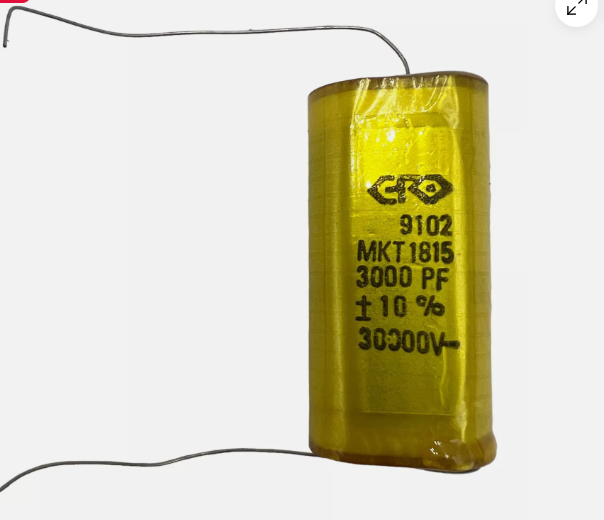
First step, super caps !! Need to test them, but will see what can be done with... 30kV caps 
Never heard of EFO caps, anyway will put them under stress before
ebay stuff, I hope size will not be to big,
https://ebay.us/FBfJnt
I trust more this than aliexpress obscur caps
| Description: |
|
| Filesize: |
137.68 KB |
| Viewed: |
1254 Time(s) |
|
|
|
| Back to top |
|
|
Curt Palme
CRT Tech
Joined: 08 Mar 2006
Posts: 24396
Location: Langley, BC
TV/Projector: All of them!
|
| Posted: Sat Aug 03, 2024 1:21 am Post subject: |
|
|
|
Well, if you get this working, you will have a (short) lineup of clients wanting spares. Good luck!
|
|
| Back to top |
|
|
Dancrt
Joined: 16 Sep 2017
Posts: 88
|
| Posted: Sat Aug 03, 2024 8:52 am Post subject: |
|
|
Best of luck following  
|
|
| Back to top |
|
|
|
|
|
|
|
You cannot post new topics in this forum
You cannot reply to topics in this forum
You cannot edit your posts in this forum
You cannot delete your posts in this forum
You cannot vote in polls in this forum
You cannot attach files in this forum
You can download files in this forum
|
Forum powered by phpBB © phpBB Group
|
|


