| Author |
Message |
MarchingCRT
Joined: 14 Nov 2008
Posts: 36
Location: Baltimore, MD
|
| Posted: Fri Dec 23, 2016 3:24 pm Post subject: Installing new boards |
|
|
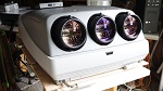
My brother bought a set of boards from Curt to update his old 8000 to the latest greatest. The tubes are excellent, just the rest of the machine gave up!
I am going to help him do this- I think we have enough experience tinkering with stuff to accomplish the task.
1. Where do I start?
2. Can I leave the machine ceiling mounted or should we figure out how to get it down.
3. Will the tubes have to come out?
Thanks!
_________________
Trombone player by day. CRT nut by night.
|
|
| Back to top |
|
 |
Curt Palme
CRT Tech
Joined: 08 Mar 2006
Posts: 24396
Location: Langley, BC
TV/Projector: All of them!
|
| Posted: Fri Dec 23, 2016 3:41 pm Post subject: |
|
|
No, take it down! You'll need to strip down the chassis an tubes to get to the motherboard under the tubes, that's the biggest thing you need to do. Swap out all boards, and fire up. I'd fire the set up with the red HV of the red tube only connected to the HV splitter, leave the G and B tubes out. Reason being is just in case something was done incorrectly, and you smoke a tube, the red one is easy to come by. If the set powers up and down and shows a pix of the red tube (G and B need to be connected to the chassis, just leave out the HV lead), then connect the G and B tubes.
Biggest thing is to put the white wire back on the right pin of each CRT. Failure to do that, and you'll nuke the tube.
Also I think you emailed me regarding the anamorphic mod. That's already done with the Ultra sets.
Cheers!
|
|
| Back to top |
|
|
MarchingCRT
Joined: 14 Nov 2008
Posts: 36
Location: Baltimore, MD
|
| Posted: Fri Dec 23, 2016 4:19 pm Post subject: |
|
|
ok. sounds pretty straight forward. When I put the tubes back in, is there a distance from lens to tube to start from. Is there a trick to getting them back or pretty close back to where they were before I took them out?
Thanks!
_________________
Trombone player by day. CRT nut by night.
|
|
| Back to top |
|
|
Jeremy112
Joined: 28 Sep 2006
Posts: 2649
Location: Fond du Lac, WI
|
| Posted: Fri Dec 23, 2016 5:00 pm Post subject: |
|
|
Tubes only fit in where they were originally mounted, I don't think I've ever seen a CRT projector where you could move the tube forward or backwards. Its a fixed mounting position, so you shouldn't have to worry about the tube being in the wrong place as long as you put it in like the old one came out 
_________________
When I'm asking for a Model number, that doesn't mean I'm asking for a nude photo with your number on it 
|
|
| Back to top |
|
|
racerxnet
Joined: 20 Jun 2007
Posts: 362
Location: Illinois
|
| Posted: Fri Dec 23, 2016 6:07 pm Post subject: |
|
|
The lens is stationary on the 8500 and the tube assembly moves with the allen screws. Top and bottom lens mount is pinned. It does swing around the pin axis though.
MAK
|
|
| Back to top |
|
|
MarchingCRT
Joined: 14 Nov 2008
Posts: 36
Location: Baltimore, MD
|
| Posted: Sat Dec 24, 2016 12:55 am Post subject: |
|
|
We have the machine down and partially disassembled. Working on the tube. The neck board does not slide onto the tube. It needs a little corner trimmed out. Is that ok to do? What should I use to do that. You can see on the picture where I have marked to cut out. Not sure the picture is getting attached...
_________________
Trombone player by day. CRT nut by night.
|
|
| Back to top |
|
|
draganm
Joined: 08 Mar 2006
Posts: 8990
Location: Colorado
|
| Posted: Sat Dec 24, 2016 1:24 am Post subject: |
|
|
| MarchingCRT wrote: | | We have the machine down and partially disassembled. Working on the tube. The neck board does not slide onto the tube. It needs a little corner trimmed out. Is that ok to do? What should I use to do that. You can see on the picture where I have marked to cut out. Not sure the picture is getting attached... |
that means it's a 9" neck-board = 9500LC
|
|
| Back to top |
|
|
MarchingCRT
Joined: 14 Nov 2008
Posts: 36
Location: Baltimore, MD
|
| Posted: Sat Dec 24, 2016 1:31 am Post subject: |
|
|
Does that mean I just put back the original neck board?
not successfully figuring out how to add a picture..
_________________
Trombone player by day. CRT nut by night.
|
|
| Back to top |
|
|
cmjohnson

Joined: 03 Apr 2006
Posts: 5180
Location: Buried under G90s
|
| Posted: Sat Dec 24, 2016 2:15 am Post subject: |
|
|
If you can't put the card on the pins because you'd have to notch out the corner, that usually means that the card is meant for use on 8" tubes, but they can be used on 9" tubes if you file out the corner to fit. The only real difference is that the beam current limiter
is set to a lower value for an 8" tube.
I've seen some inconsistency in this. I have 9" tubes that have no notch clipped out of the plastic, and I have 9" tubes that do
have the notch clipped out. So I would not say that the notch ALWAYS means 8" card or 9" card.
But if your PJ is an 8000 then odds are that your neck cards are the very old 50-2005 or 50-2013 series. Those are not the cards anybody wants. You want to use 50-2038 or 50-2039 series cards if you have them or can get them. Much better cards.
The biggest thing about the upgrade is that you add electronic astic to the machine. That requires new focus yokes which have TWO cables leading out of them, not one. The astig board needs to be added to the rear heatsink and the stigmator waveform generator daughterboard needs to be put on the CLM. CLM firmware also needs to be a high enough version to support astig. (3.1 is certainly new enough, anything newer of course will.)
|
|
| Back to top |
|
|
MarchingCRT
Joined: 14 Nov 2008
Posts: 36
Location: Baltimore, MD
|
| Posted: Sat Dec 24, 2016 3:13 am Post subject: |
|
|
The new neck cards are 50-2039. I want to make sure it is ok to put the notch in it so it will slide onto 8 inch tubes and that it is only a physical issue and not an electronic one as well. What is the best way to accomplish making that notch?
Curt sent all newer boards power supplies and the focus yokes with the two leads.
Thanks for your help!
_________________
Trombone player by day. CRT nut by night.
|
|
| Back to top |
|
|
cmjohnson
Joined: 03 Apr 2006
Posts: 5180
Location: Buried under G90s
|
| Posted: Sat Dec 24, 2016 4:00 am Post subject: |
|
|
|
Use a fine tooth file and just file out the notch.
|
|
| Back to top |
|
|
Treyson
Joined: 02 Feb 2016
Posts: 3
Location: Village Mills, TX
TV/Projector: Marquee 8000
|
| Posted: Sat Dec 24, 2016 4:20 am Post subject: |
|
|
|
Thanks guys! We were hoping that was the solution, just didn't want to do something drastic and really screw up! I'm sort of good at that already🤔
|
|
| Back to top |
|
|
MarchingCRT
Joined: 14 Nov 2008
Posts: 36
Location: Baltimore, MD
|
| Posted: Sat Dec 24, 2016 8:58 pm Post subject: |
|
|
We have the new boards in and the machine all back together. We fired it up and nothing blew up, but the image has horizontal lines scrolling up on all three tubes. Blue not as bad as green and red. They are present on the video image and on internal test patterns. And the image seems to have a bit of judder, maybe that is what I am seeing because of the lines.
I reinitialized and no difference. Any ideas on that one?
Thanks,
Trent
_________________
Trombone player by day. CRT nut by night.
|
|
| Back to top |
|
|
Curt Palme
CRT Tech
Joined: 08 Mar 2006
Posts: 24396
Location: Langley, BC
TV/Projector: All of them!
|
| Posted: Sat Dec 24, 2016 9:47 pm Post subject: |
|
|
|
Post a video please.. do the internal test patterns do it? Sounds like you're close..
|
|
| Back to top |
|
|
draganm
Joined: 08 Mar 2006
Posts: 8990
Location: Colorado
|
| Posted: Sun Dec 25, 2016 8:38 pm Post subject: |
|
|
| MarchingCRT wrote: | We have the new boards in and the machine all back together. We fired it up and nothing blew up, but the image has horizontal lines scrolling up on all three tubes.
Trent |
sounds like noise from the tube grounding straps.
Where did you plug in the 2 big Fat Black wires that feed back from the tube-bell in front?
| MarchingCRT wrote: | | Not successfully figuring out how to add a picture.. |
after you hit "reply" scroll dow nto the bottom of the page and click on "add attachments" , then "browse" which should take you to your desktop on your PC or your file folders.
pick the pic you want to attach, double click it, and then back on the web-site hit "upload",
Click "preview post " before posting ot make sure it's attached to you reply
|
|
| Back to top |
|
|
cmjohnson
Joined: 03 Apr 2006
Posts: 5180
Location: Buried under G90s
|
| Posted: Sun Dec 25, 2016 9:07 pm Post subject: |
|
|
Horizontal bars slowly moving up or down are noise bars. Disconnect ALL external equipment from the projector and check again.
That means nothing is connected to it but the power cord itself. Not one other cable to any other device.
But if you have brighter diagonal lines running across the CRT faces, G2 is way too high or uncontrolled and it needs to be controlled before shutting down the projector. If all else fails pull the P14 plug on the side of the motherboard under the blue tube's neck card cage, which will remove filament voltage. When the image completely fades away you can then turn off power safely.
Turning off the PJ with the bright diagonal lines of a G2 failure displayed will result in a spot burn on the affected tube.
Make SURE you put the white flying leads on the neck cards on pin 2 of the tubers. Looking at the pin end of the tube, two pins
are in the white plastic pocket all by themselves. Pin 2 is the more CLOCKWISE pin. The white flying lead belongs on pin 2 of those tubes if you have stock 180DMB type tubes.
Do NOT forget, or ignore, those tube grounding straps. They are there for a reason, and they must lead to chassis ground. The
tubes otherwise will build up a voltage of up to a few thousand volts and eventually arc over to something else which may be electronic and which may react badly to getting zapped. All grounds on the tube housings need to eventually connect to the
rear heat sink. Do not forget the two black ground straps in the tube housing that connect to the ground tabs on the neck card,
and do not forget to screw the white flying ground lead with ring lug to the tube shield cover and the ground straps.
|
|
| Back to top |
|
|
MarchingCRT
Joined: 14 Nov 2008
Posts: 36
Location: Baltimore, MD
|
| Posted: Sun Dec 25, 2016 10:31 pm Post subject: |
|
|
you two were right on. all six black straps were not seated completely. works much better now :-0
now onto the magnets... I have tweaked mine before, but now we are starting from scratch. I have Bill Blue's guide and have followed it before. Will take it slowly and patiently.
Is there a starting place for the tubes for the focusing? i.e top bolt "x" turns and bottom right x turns?
Thanks!
_________________
Trombone player by day. CRT nut by night.
|
|
| Back to top |
|
|
racerxnet
Joined: 20 Jun 2007
Posts: 362
Location: Illinois
|
| Posted: Mon Dec 26, 2016 2:35 pm Post subject: |
|
|
| MarchingCRT wrote: | you two were right on. all six black straps were not seated completely. works much better now :-0
now onto the magnets... I have tweaked mine before, but now we are starting from scratch. I have Bill Blue's guide and have followed it before. Will take it slowly and patiently.
Is there a starting place for the tubes for the focusing? i.e top bolt "x" turns and bottom right x turns?
Thanks! |
When I mounted the HD-144 lenses I checked the distance from back lens to tube face and was about .100 thousandths. Allen screw was 7 to 8 full turns from start and the adjusting knobs were centered. Not sure where the HD-8 lenses need to be, but that was a start for me. I left the knobs stationary and used the allen screws to adjust focus reasonably. Then use the knob for final tweaking. The further distance from the tube face the less centered the adjusting knobs will be.
MAK
|
|
| Back to top |
|
|
|
|


