| Author |
Message |
cmjohnson

Joined: 03 Apr 2006
Posts: 5180
Location: Buried under G90s
|
| Posted: Sat Jun 18, 2016 4:41 am Post subject: |
|
|
|
Are your tubes LCPs or LUGs? I can't remember if you mentioned that.
|
|
| Back to top |
|
 |
thewolfman

Joined: 28 Mar 2011
Posts: 1311
Location: Sweden
|
| Posted: Sat Jun 18, 2016 6:58 am Post subject: |
|
|
|
I have LCPs. But these VNB will handle both LCPs and LUGs without any more modification made to them. I'm told it doesn't matter what I use and that they are special that way. If I remember correctly. So in the future, I could get another set from you seeing you have so many that they will last a long time. I hope you get that ICE CLEAR to use in your tubes, btw, because that would make them more valuable I guess. I don't want to mess with that personally but wonder how much of an effect that would have over normal glycol. I should read up on that.
|
|
| Back to top |
|
|
cmjohnson
Joined: 03 Apr 2006
Posts: 5180
Location: Buried under G90s
|
| Posted: Sat Jun 18, 2016 11:22 am Post subject: |
|
|
I got almost 10 years out of regular old glycol-ethanol mix when the front plate was treated with VHT epoxy (Nash's idea, to give proper credit) so I don't feel any compelling need to switch to ice clear. It MIGHT be better but I figure that if regular coolant can last 10 years with painted front plates, then that's probably going to outlast the useful life of the projector. In 10 years I think
that we'll all look back at our CRT years with nostalgia, but won't have seen one running for several years.
I mod every neck board for LCP or LUG tubes as well. Why not? It's easy, quick, and besides, I am repairing a pile of neck cards
and they all have to be tested after repair, and my test unit only has LUGs in it.
I'm not doing the extensive LUG mod that Mike does, but I do change out R38 for a 4.7 megohm resistor, move the heater wires to the back of the board, and drill out the pin 6 socket hole after removing the socket.
|
|
| Back to top |
|
|
mp20748
Joined: 12 Sep 2006
Posts: 5689
Location: Maryland
TV/Projector: 9500LC Ultra / Super 02 and 03 VIM
|
| Posted: Sat Jun 18, 2016 12:55 pm Post subject: |
|
|
| cmjohnson wrote: | I got almost 10 years out of regular old glycol-ethanol mix when the front plate was treated with VHT epoxy (Nash's idea, to give proper credit) so I don't feel any compelling need to switch to ice clear. It MIGHT be better but I figure that if regular coolant can last 10 years with painted front plates, then that's probably going to outlast the useful life of the projector. In 10 years I think
that we'll all look back at our CRT years with nostalgia, but won't have seen one running for several years |
With that I hate to tell you this, but my testing this week confirms what I had been thinking about this "standard" or the glycol solution we have been using:
The stuff is fine for general use, but fails in the LUG tube when going 1920X1080 60 or anything higher. It's should really be labeled "Not for High Resolution use" and this is especially the case with the LUG tubes. The LUG produces a smaller dot (pixel) size that gets distorted when using the standard glycol and projecting on the screen. I would think some were blaming this on the lens, but that's not the case. The lens do well, it's the glycol that distorts the finer lines of pixel structure.
So I'm going Ice Clear for sure.
| Quote: | | I'm not doing the extensive LUG mod that Mike does, but I do change out R38 for a 4.7 megohm resistor, move the heater wires to the back of the board, and drill out the pin 6 socket hole after removing the socket. |
I convert the original neck boards for LUG without drilling holes, and it's done without using the white wire. I wire pin 7 to the G2 supply on the board itself. So the neck board would be LUG ready, with the white wire only being necessary when using LCP's.
|
|
| Back to top |
|
|
cmjohnson
Joined: 03 Apr 2006
Posts: 5180
Location: Buried under G90s
|
| Posted: Sat Jun 18, 2016 1:00 pm Post subject: |
|
|
I see what you're saying about the glycol, and high resolution. It's something I'll look into.
I did do some experiments on mix ratios and found that if the mix ratio has too much glycerin in it, you get a "squirm" effect,
which you can see if you just shine a light through it. As long as glycerin doesn't exceed 20 percent of the mix, by volume,
then the squirm effect goes away. So at the very least I would say that if a glycol/glycerin mix is to be used with LUG tubes,
it should be an 80/20 glycol/glycerin mix, or even have less glycerin in it.
Have you compared an 80/20 mix to the iceclear?
|
|
| Back to top |
|
|
mp20748
Joined: 12 Sep 2006
Posts: 5689
Location: Maryland
TV/Projector: 9500LC Ultra / Super 02 and 03 VIM
|
| Posted: Sat Jun 18, 2016 1:10 pm Post subject: |
|
|
[quote="cmjohnson"
Have you compared an 80/20 mix to the iceclear?[/quote]
No, and probably won't. I'm waiting on the Ice Clear, but can tell you from when I had the Ice Cear in my red CRT some years back, its definitely clearer than any glycol solution I've seen. Plus it does not blur or distort the image as what you see with the glycol solutions. You won't see or notice any of this until you're able to get those very finer details on the tube surface itself.
|
|
| Back to top |
|
|
cmjohnson
Joined: 03 Apr 2006
Posts: 5180
Location: Buried under G90s
|
| Posted: Sat Jun 18, 2016 1:17 pm Post subject: |
|
|
I will try some out. Better to figure it out now before I buy more gallons of glycol and glycerin!
I recently discontinued the practice of automatically adding coolant to every tube assembly as I build them. Some may sit for
years before they're installed in a projector, why let the coolant age in the chamber when it's not even being run?
I'm getting about 7 fills per mixed gallon. (Gallon of gylcol plus a quart of glycerin) I've got enough work on hand to need five more gallons of mix, if not more. If iceclear is comparable in price, then it's a no brainer. Buy that instead.
|
|
| Back to top |
|
|
greg9518lc

Joined: 19 Apr 2016
Posts: 360
|
| Posted: Sat Jun 18, 2016 4:05 pm Post subject: |
|
|
5 gallons 77.00 shipped to your door you do the math???????????????
_________________
VDC 9518LC modded: I do not sell or promote mods only interested in the best PQ possible......
|
|
| Back to top |
|
|
racerxnet
Joined: 20 Jun 2007
Posts: 362
Location: Illinois
|
| Posted: Sat Jun 18, 2016 4:25 pm Post subject: |
|
|
I can confirm that the internal menus do not always display correctly with the modded neckboards and VIM. Some of the letters are broken or missing. Pushing the Help button for the next page may display fine. Its is random which page displays OK. The source image with my PC at 1080p is always good. Just thought that this info may help.
MAK
|
|
| Back to top |
|
|
mp20748
Joined: 12 Sep 2006
Posts: 5689
Location: Maryland
TV/Projector: 9500LC Ultra / Super 02 and 03 VIM
|
| Posted: Sat Jun 18, 2016 6:01 pm Post subject: |
|
|
| racerxnet wrote: | I can confirm that the internal menus do not always display correctly with the modded neckboards and VIM. Some of the letters are broken or missing. Pushing the Help button for the next page may display fine. Its is random which page displays OK. The source image with my PC at 1080p is always good. Just thought that this info may help.
MAK |
Other than what's written in this thread about this, and I'm sure its Q2 being shorted that causes this problem. This is the first time I'm hearing about or have seen a problem like this with the later boards.
Because this versions gets its its timing reference from the Moome card, the left side of the internal patterns would show missing when the external source is being used. The left side would be present when in the internal patterns. And that is what Wolfman is also seeing.. the internals are correct, bright and text in order with the source being the problem. That is usually a Q2 problem. That normally happens when a tube arcs or there is high voltage leaking in the set.
|
|
| Back to top |
|
|
greg9518lc
Joined: 19 Apr 2016
Posts: 360
|
| Posted: Sat Jun 18, 2016 6:22 pm Post subject: |
|
|
[quote="mp20748"][quote="racerxnet"]I can confirm that [b]the internal menus do not always display correctly with the modded neckboards and VIM. Some of the letters are broken or missing[/b]. Pushing the Help button for the next page may display fine. Its is random which page displays OK. The source image with my PC at 1080p is always good. Just thought that this info may help.
MAK[/quote]
Other than what's written in this thread about this, and I'm sure its Q2 being shorted that causes this problem. This is the first time I'm hearing about or have seen a problem like this with the later boards.
Because this versions gets its its timing reference from the Moome card, the left side of the internal patterns would show missing when the external source is being used. The left side would be present when in the internal patterns. And that is what Wolfman is also seeing.. the internals are correct, bright and text in order with the source being the problem. That is usually a Q2 problem. That normally happens when a tube arcs or there is high voltage leaking in the set.[/quote]
My menus are 100% fine
_________________
VDC 9518LC modded: I do not sell or promote mods only interested in the best PQ possible......
|
|
| Back to top |
|
|
barclay66

Joined: 27 Jun 2011
Posts: 1304
Location: Germany
TV/Projector: Marquee 9500 Ultra
|
| Posted: Mon Jun 27, 2016 8:42 am Post subject: |
|
|
Hi,
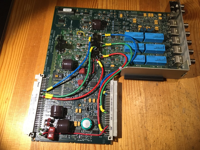
Last week I received the MP-modded VIM from thewolfman. It was packed with a great deal of care, so I would assume that the shipment didn't do any further harm.
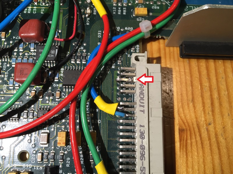
After visual inspection I discovered that one of the contacts on the Moome connector had been pushed out of the housing. It would be pushed out even more with the Moome card installed. I removed the contact, bent it back to its original shape and soldered it back in. With additional solder, I reinforced its back so it won't be pushed out again. The signal on this contact is V-Sync. I think it still made contact as otherwise the picture wouldn't have been stable. So I don't think it is related to the problems that thewolfman experienced.
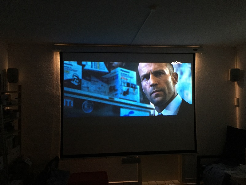
On my test machine I first took some pictures with a -03 VIM (my backup board, only modified for supply voltage filtering) in order to have some reference value for brightness and contrast:
- Signal source was HD-TV receiver (720p50)
- Signal path: HD-TV -> 4to1 switcher -> 1to2 splitter -> Moome card
- G2 levels adjusted, contrast at 75, brightness at 65
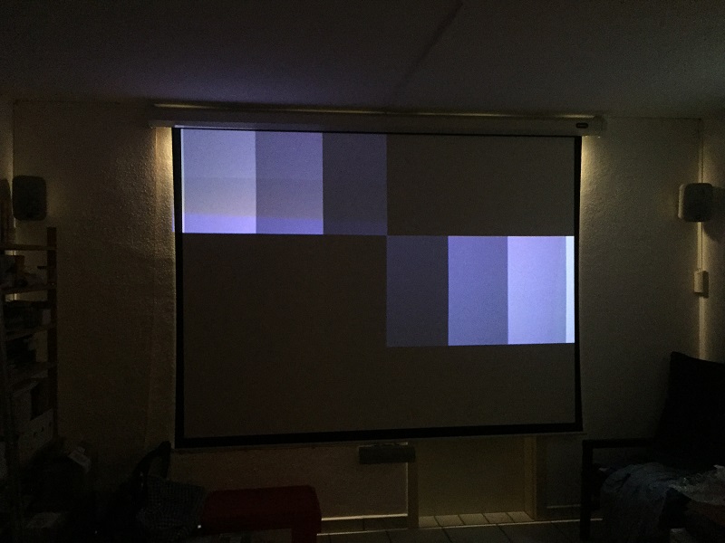
Then I mounted the MP-modded VIM. The picture became very dark (less than 50% brightness). Otherwise, the picture content was complete, sharp and without streaking or smearing. Contrast and brightness setting range wasn't enough for bringing up enough brightness. I didn't play with the G2 settings.
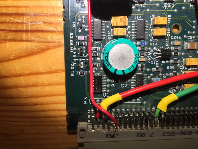
I measured Q2 and it was shorted. I replaced it with another PNP transistor I had at hand (BC640) but this didn't change anything. I will try again with the original type (I will have to take one from another board).
@Mike: Any measurements that I should perform?
I made some pictures (screenshots appear grainy due to camera limitations):
01_Normal_VIM.JPG
My backup VIM showing some HD-TV picture
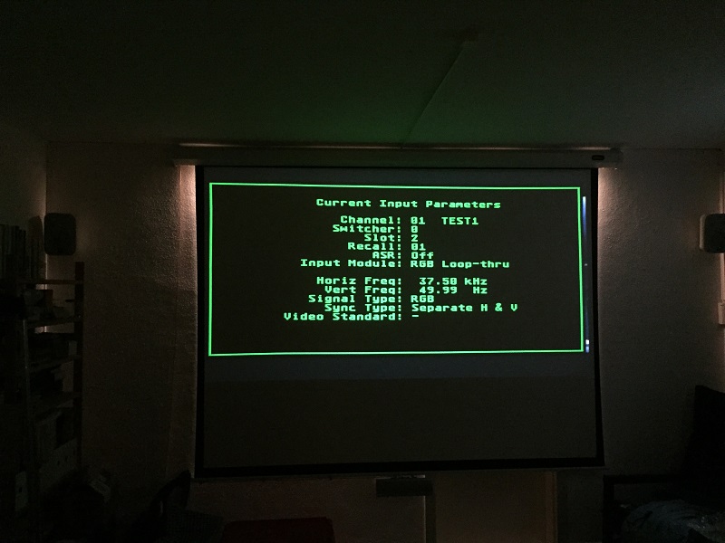
02_Normal_VIM.JPG
My backup VIM showing menu & settings
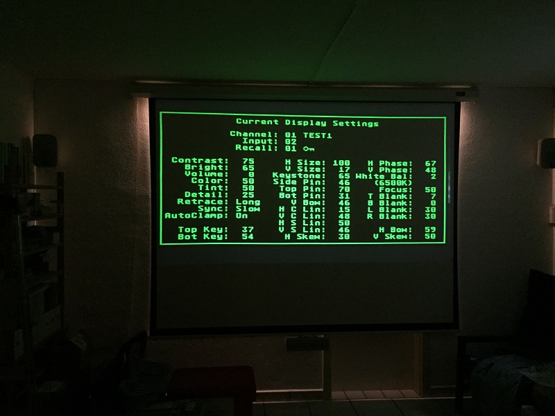
03_Normal_VIM.JPG
My backup VIM showing menu & settings
04_Inspection.JPG
The MP-modded VIM as I received it
05_V-Sync_Pin.JPG
Pushed out contact
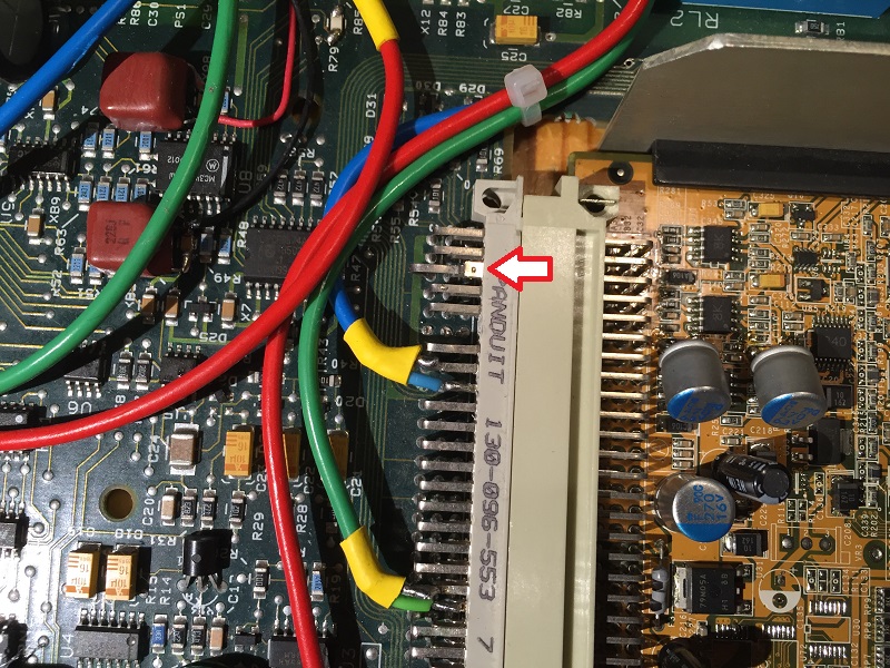
06_V-Sync_Pin.JPG
Pushed out contact with Moome mounted
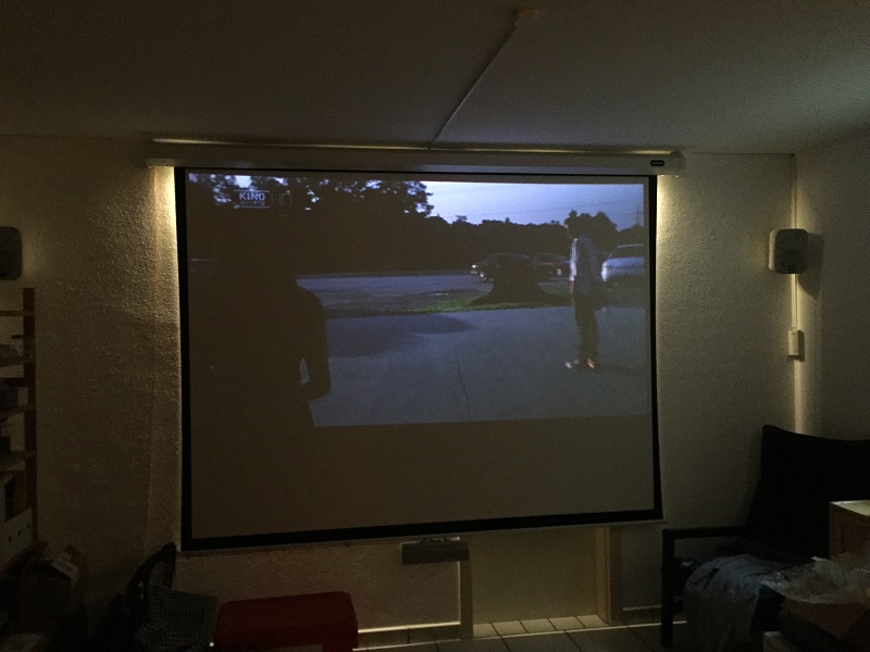
07_VIM_Test.JPG
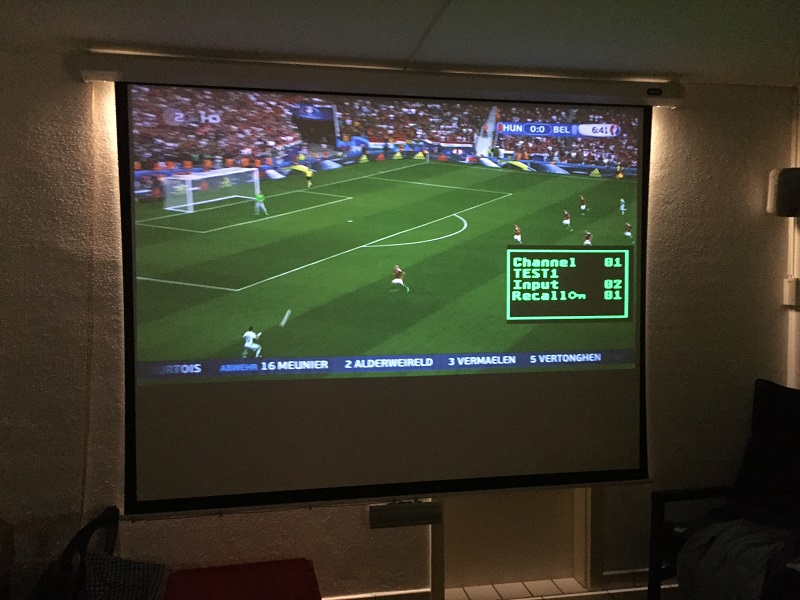
MP-modded VIM showing HD-TV picture. Notice the additional grain in the photo (not on screen) and the brighter back light. This effect is due to the camera adjusting to the overall lower brightness.
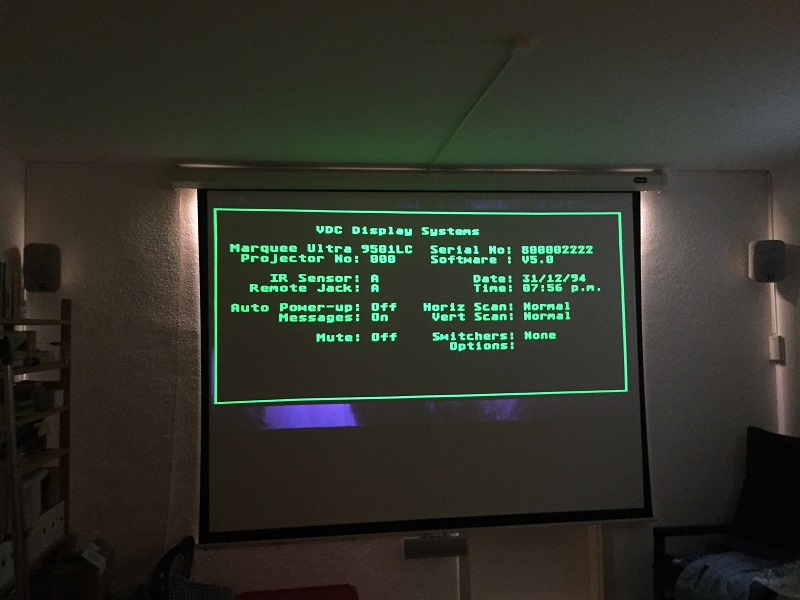
08_VIM_Test.JPG
MP-modded VIM showing menu & settings. The brightness of the menus is almost as high as with the backup VIM.
09_VIM_Test.JPG
MP-modded VIM showing the grey scale test pattern (quite dark).
10_VIM_Test.JPG
MP-modded VIM showing HD-TV picture with a menu item. Sharpness is fine and menu items are perfectly visible.
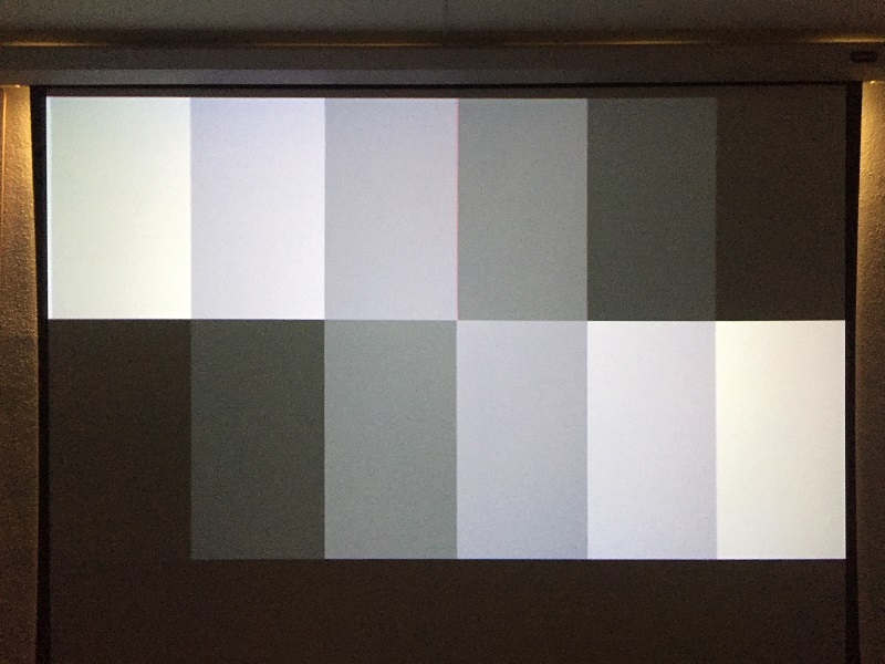
11_Reference.JPG
Grey scale pattern on my own Marquee for reference.
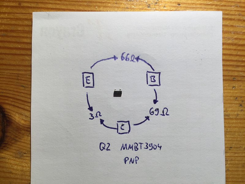
12_Q2_Results.JPG
Measurements on Q2.
| Description: |
|
| Filesize: |
131.47 KB |
| Viewed: |
12451 Time(s) |
|
| Description: |
|
| Filesize: |
112.5 KB |
| Viewed: |
12451 Time(s) |
|
| Description: |
|
| Filesize: |
130.07 KB |
| Viewed: |
12451 Time(s) |
|
| Description: |
|
| Filesize: |
267.16 KB |
| Viewed: |
12451 Time(s) |
|
| Description: |
|
| Filesize: |
231.36 KB |
| Viewed: |
12451 Time(s) |
|
| Description: |
|
| Filesize: |
280.07 KB |
| Viewed: |
12451 Time(s) |
|
| Description: |
|
| Filesize: |
125.19 KB |
| Viewed: |
12451 Time(s) |
|
| Description: |
|
| Filesize: |
133.53 KB |
| Viewed: |
12451 Time(s) |
|
| Description: |
|
| Filesize: |
112.59 KB |
| Viewed: |
12451 Time(s) |
|
| Description: |
|
| Filesize: |
161.89 KB |
| Viewed: |
12451 Time(s) |
|
|
|
| Back to top |
|
|
barclay66
Joined: 27 Jun 2011
Posts: 1304
Location: Germany
TV/Projector: Marquee 9500 Ultra
|
| Posted: Mon Jun 27, 2016 8:44 am Post subject: |
|
|
Last two pictures shown here due to 10 pic limitation per post.
| Description: |
|
| Filesize: |
145.5 KB |
| Viewed: |
12445 Time(s) |
|
| Description: |
|
| Filesize: |
153.1 KB |
| Viewed: |
12446 Time(s) |
|
|
|
| Back to top |
|
|
mp20748
Joined: 12 Sep 2006
Posts: 5689
Location: Maryland
TV/Projector: 9500LC Ultra / Super 02 and 03 VIM
|
| Posted: Mon Jun 27, 2016 10:54 am Post subject: |
|
|
There should have been a very big difference when you replaced Q2. Try that using another 02 VIM to see the results. And with no noticeable after changing Q2, that means the circuit is not doing what it should, try replacing with same type.
Your or another VIM would have a different Internal Pattern from the modified because they both use different pedestal references. The MP 02 does not use the references on the VIM (entire first stage out - entire internal pattern section also out). The reference for the internal pattern comes off the CLM and the reference for the External Source (moome) comes off the Moome. So there are NO pedestal (black reference) circuits on the MP 02. So the black or reference level would be a single and what is on the sources only.
Therefore a stock or VIM that uses both on-board pedestal circuits would look very different, and could need G2 and other touch-up. But at this point, Q2 is still at question because when it's not doing what its supposed to do, the image will be dark.
Other than the darkness problem, which to me I knew would be Q2, I was also concerned about the distorted text that he showed in his shots. I'm not seeing that in your shots though.
|
|
| Back to top |
|
|
barclay66
Joined: 27 Jun 2011
Posts: 1304
Location: Germany
TV/Projector: Marquee 9500 Ultra
|
| Posted: Mon Jun 27, 2016 11:33 am Post subject: |
|
|
OK, will replace Q2 with the original type. I have some part-donor boards where the MMBT3906 is being used.
I don't think that one of the previous stages has a problem, as a faulty U2 would interfere with several other functions (like scan fail etc.). Will report back after having tested again. BTW: Auto-clamp is set to "ON". Could this setting have any influence?
Regards,
barclay66
|
|
| Back to top |
|
|
mp20748
Joined: 12 Sep 2006
Posts: 5689
Location: Maryland
TV/Projector: 9500LC Ultra / Super 02 and 03 VIM
|
| Posted: Mon Jun 27, 2016 11:53 am Post subject: |
|
|
| barclay66 wrote: | OK, will replace Q2 with the original type. I have some part-donor boards where the MMBT3906 is being used.
I don't think that one of the previous stages has a problem, as a faulty U2 would interfere with several other functions (like scan fail etc.). Will report back after having tested again. BTW: Auto-clamp is set to "ON". Could this setting have any influence?
Regards,
barclay66 |
"auto clamp" should only work with the Composite input module, if my memory serves me right. So it shouldn't play a role here.
Not sure what you mean by "U2" or did you mean "Q2" - a faulty Q2 I'm not aware of to cause any scan fail, but for sure it provides a very important pulse (clamping) for the VIM. May not be necessary for this version I would need to check.
But the levels would be very different from a stock VIM with this version.
Try remove from one of your VIMs and see what happens
|
|
| Back to top |
|
|
barclay66
Joined: 27 Jun 2011
Posts: 1304
Location: Germany
TV/Projector: Marquee 9500 Ultra
|
| Posted: Mon Jun 27, 2016 12:12 pm Post subject: |
|
|
Hi,
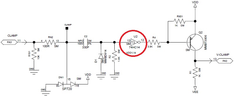
I was thinking about U2 (74HC14) which provides the signal to Q2. Other parts of U2 are being used for the generation of spotkill and other related signals (e.g. derived from scan fail signals). Therefore I thought: If U2 is bad we would have a very different situation...
Regards,
barclay66
| Description: |
|
| Filesize: |
39.57 KB |
| Viewed: |
12391 Time(s) |
|
|
|
| Back to top |
|
|
mp20748
Joined: 12 Sep 2006
Posts: 5689
Location: Maryland
TV/Projector: 9500LC Ultra / Super 02 and 03 VIM
|
| Posted: Mon Jun 27, 2016 2:25 pm Post subject: |
|
|
Ok it's using part of that chip.
Not sure why I'm seeing the left edge of the OSD when the Moome is the source. That VIM should not show that left edge.
|
|
| Back to top |
|
|
mp20748
Joined: 12 Sep 2006
Posts: 5689
Location: Maryland
TV/Projector: 9500LC Ultra / Super 02 and 03 VIM
|
| Posted: Mon Jun 27, 2016 5:25 pm Post subject: |
|
|
There's a lot here that I'm not able to follow. For one, it's the first time I've had testing where I was not asked anything about the VIM before hand, to include, I'm not sure why the VIM was tested using the previous setup as a reference.
If the two boards were technically identical, I would follow somewhat. But with one being an almost entirely different circuit design with NO settings made to show how to make it look better. I can't figure out what would be the point. Normally I would have been asked especially with it being a very different circuit design; "what to look for and what test should I do"
Also, I asked about the left edge not showing in the shots that are using the MP 02 VIM, because that VIM should not show an Moome or external image with it's OSD menu showing the left edge. That left edge can be seen in Wolfman's shots earlier using that same VIM. I just wanted to know what happen to make that shot show a full OSD.
The gain on that VIM is lower than a stock, much lower and I've been explaining that to those who have it, and that there is a reason for it being lower.
It works very different because it is very different, in both design and how it should be setup and used.
At this point, ship that VIM back to him, I'll be sending him another one. Thanks for your help
|
|
| Back to top |
|
|
barclay66
Joined: 27 Jun 2011
Posts: 1304
Location: Germany
TV/Projector: Marquee 9500 Ultra
|
| Posted: Mon Jun 27, 2016 7:51 pm Post subject: |
|
|
Mike,
Sorry, but I fail to understand what Your intentions are. First, You agree to me testing the board, then something doesn't turn out as You've been expecting it and now You're calling everything off?
I've asked twice (once initially and once I received the VIM) if You wanted me to test anything in particular. Except for the issue with Q2 and You explaining that this board is so much different, I haven't been able to see any kind of instruction like "...use this or that input signal and test this or that..." or similar. If the behaviour of the menus isn't the one You're expecting, then sorry, but I'm not responsible. I'm just able to test it in one of my mostly stock machines, explain the testing circumstances and show the results. I'm not the one that's expected explaining them.
If there's a special kind of preparation needed before using this VIM, then please explain it to me.
I happily will support You with any kind of tests and/or measurements as long as You will tell me what You're interested in and as long as my equipment and capabilities will allow me to.
But now back to topic:
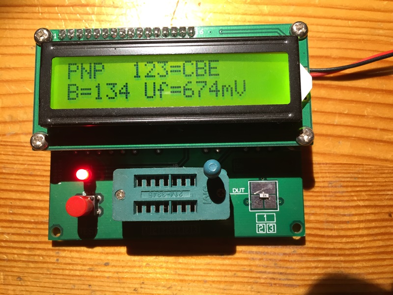
I did replace Q2 with the original type. Before putting it in I tested it too (Pictures Transistor_Test.JPG and Q2_replaced.JPG).
Now there's some more brightness but still much lower than on a stock VIM. If I set both to the same settings (G2 around 60-62, contrast at 65 and brightness at 60) the modded VIM will produce about 60-70% of a stock VIM's brightness.
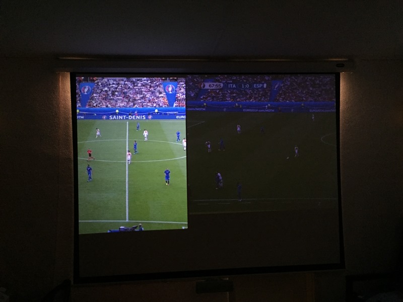
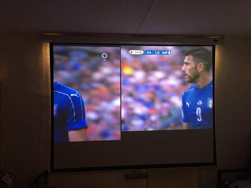
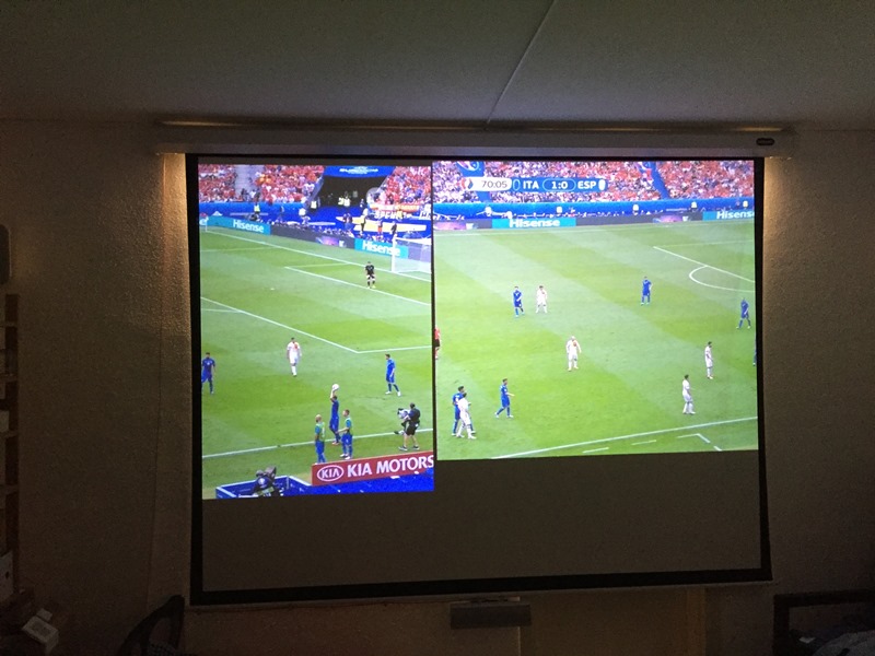
I was able to produce some kind of side-by-side comparision. I used the picture phase and blanking adjustments in order to move the pictures from my regular and my test machine next to each other onto the same screen. Left is my regular Marquee, right is the test machine. With this, the difference in brightness becomes much more visible (Picture Side-byside_01.JPG).
If I crank up contrast to 100 and brightness to 90 on the test machine then I almost get the same brightness level on both (Pictures Side-byside_02.JPG and Side-byside_03.JPG). At this setting, the menus will show intense blooming.
I tried raising the G2 levels. This is quite difficult as the internal test patterns are much brighter than the source. So I went for an optical reference and raised them until I would get the same amount of brightness compared to my regular machine (adjusting each color of the test machine to the two colors of the regular one using an external pattern). G2 levels ended at about 70 and now yielded enough light output. But: With these settings I wouldn't get any blacks and the picture didn't have punch. Maybe there's an upper limit to the G2 settings that shouldn't be surpassed. A detailed setup procedure which takes into account the special characteristics of the modded VIM could be handy.
Another bit of information: If You go into the super secret menu and try to adjust the brightness of the menus ("Adjust Internal Video") You can tune down their brightness in order to avoid them blooming. A good value would be around 35 (default level is 70). Interesting: The brightness of the source increases with lowering the brightness of the menus and vice versa...
Regards,
barclay66
| Description: |
|
| Filesize: |
191.15 KB |
| Viewed: |
12320 Time(s) |
|
| Description: |
|
| Filesize: |
224.54 KB |
| Viewed: |
12320 Time(s) |
|
| Description: |
|
| Filesize: |
80.15 KB |
| Viewed: |
12320 Time(s) |
|
| Description: |
|
| Filesize: |
97.9 KB |
| Viewed: |
12320 Time(s) |
|
| Description: |
|
| Filesize: |
117.25 KB |
| Viewed: |
12320 Time(s) |
|
|
|
| Back to top |
|
|
|
|


