| Author |
Message |
the dude
Joined: 11 Sep 2013
Posts: 179
|
| Posted: Mon Feb 22, 2016 9:20 pm Post subject: HowTo: Barco 909 Neckboards in 1209s |
|
|
Hello folks,
i've been asked how i managed to put the 909 Neckboards in my 1209s. Since the original thread now deals with completly different topics i start a new now for those who are interested in doing the same. So i just deinstalled a board, made some photos and documentation.
Preface
The 909 neckboards are ideal suited to be put in a 1209s. In fact all basic signals and supply voltages are the same.
To give a start i will first explain what the differences are and what must be done:
-The 909 Neckboard has a G2 regulator. It expects the maximal G2 voltage. On the board there is a transistor that drops G2 to the correct level. This regulator is controlled by the ABL loop. This requires some small modifications on the G2/Diagnostic board to balance the G2 lines. The ABL trigger signals and the IBCL feedback is compatible.
-Since there is a filter capacitor for G2 that charges up, a G2 kill signal is required to drop G2 qickly at shutdown and scanfail. This will prevent spot burn. In the 909 this signal is provided by the G2/Diagnostic board. In the 1209s board this signal is also present, but only used on-board. This will not be enough since the capacitor will hold charge even if the G2 is down. We must connect the internal G2 kill signal to the neckboard in order to prevent spot burn. For this reason, it would be a good idea to have a burned tube for testing. If you make a mistake here it may save your tubes. For obvious reasons i havn't testet if G2 kill is really required/what would happen if ommited or if it will work in case of scan fail, so this is own your own risk of course! With an old tube everthing was fine at shutdown, so i put the whole thing in my real projector.
-The 1209 socket board has wires and a female connector attached, the 909 board has a male connector on the PCB. The pinout is exacly the same. You can remove the wires from the 1209 board and solder them to the 909 board.
The amp board has 2 pins more than the 1209s one. One is ground and one is G2 kill. Except this extra pins the connector is also the same. Therefore the little plastic guide can simply be cut of with a sharp blade at one side, and the 9 pin connector can be plugged in the 11 pin. Be sure it is inserted without any force since with a little force it can be connected wrong with only one of the plastic guides left.
-A extra connector is added for the spotkill signal and a little wire harness has to be made to distribute the signal to the neckboards.
-The mounting brackets that hold the boards don't fit. Get some 909 brackets if you can, i modified mine using a milling machine to fit the heatsink.
|
|
| Back to top |
|
 |
the dude
Joined: 11 Sep 2013
Posts: 179
|
| Posted: Mon Feb 22, 2016 9:22 pm Post subject: |
|
|
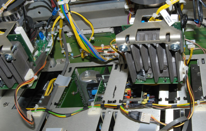
The final result. Neckboards installed in 1209s. Notice the modified brackets, the G2 kill connector and the G2 kill wire harness.
| Description: |
|
| Filesize: |
156.93 KB |
| Viewed: |
9550 Time(s) |
|
|
|
| Back to top |
|
|
the dude
Joined: 11 Sep 2013
Posts: 179
|
| Posted: Mon Feb 22, 2016 9:24 pm Post subject: |
|
|
Modifications of the G2 board
G2 Kill
First of all we need the G2 kill signal. Connect a generall purpose diode with the cathode to the emitter of Q100. The anode goes to the g2 kill line on the new G2 kill connector.
I used a 4 pole connector for that. One pin of the connector is connected to ground, one pin for G2 kill and 2 pins are used for a filament security loop. The idea is to cut off the filament voltage if the connector on the G2 board isn't seated and to cut off the filament voltage for a individual neckboard if the connector is not seated in order to prevent spot burn. I cut the FIL- voltage, just because it was nicer for the wires to connect. This is an idea you may implement, but thats up to you. Anyway, if you don't connect the amp board in a 909, the filament is still powerered, G2 is present and the cathode will be at low potential, so this may be dangerous also on a original 909.
I integrated the diode in the cable.
G2 Balancing
On the neckbords the G2 is pulled to ground, and this needs also some attention. If your tubes require different G2 voltages (assume they do!) the series resistor is much to low, and all G2 lines are affected. In my set this has caused much to low G2 for green, color balance was impossible and green was very dim. The G2 comes from the focus block that is connected to a 15 Kv line from the EHT, the focus block is just made of 2 resistors. This is a high impedance circuit, and so a single regulator can pull the whole G2 down for all tubes. This is why the 909 has a inverter for G2 generation, it provides a much lower impedance voltage source.
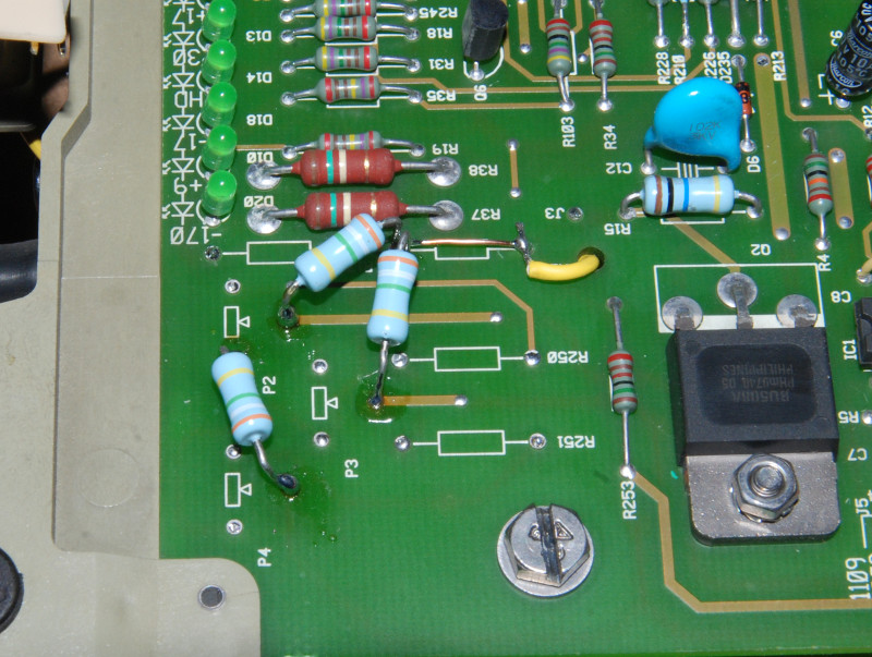
To correct this we have to avoid unessesary load on G2 first. Remove trim pots P2, P3 and P4. Remove resistors R250, R17 and R251.
Connect 1020V point (J3) to the 3 G2 lines G2_B, G2_B and G2_R using the 3,9M resistors you removed before. R252 can be replaced by straight wire in order to do that (see photo).
This should provide proper balancing.
Finally, the 15 Kv HV lead from the EHT is put into one of the focus output connectors instead of the input. This will bypass the focus resistor also, this may help a little (the focus resistor is quite low compared to the HV resistor i can't even measure - maybe there are diodes in series even if the diagram don't show any). Q2 can take the little additional load without problems.
If this does not work, one of the tubes may have a very different G2 requirement, this may indicate a problem with the tube. It may help to use higher balancing resistors in this case.
Also you may use a inverter like the 909 does to avoid balancing problems. Be sure it provides about 1Kv, ensure it will not go higher than the Uce max. of the regulator transistor. A inverter from a LCD backlight may work. You also may construct your own inverter.
But in normal cases the resistor balancing will be fine. I use a mixed set of P19LUG, PT22-22 and P19LCP and it works perfekt!
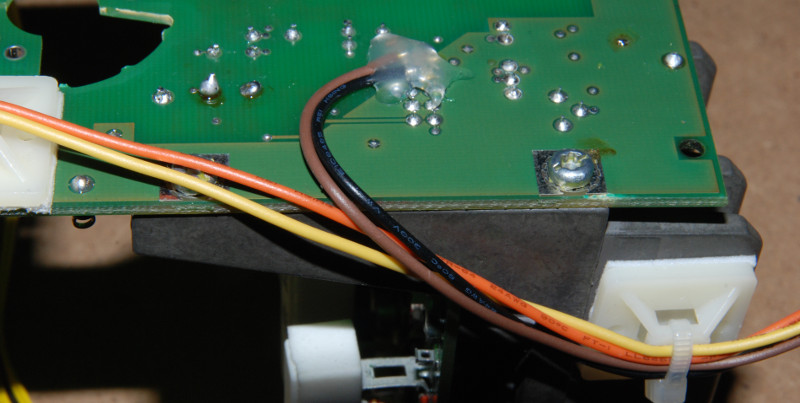
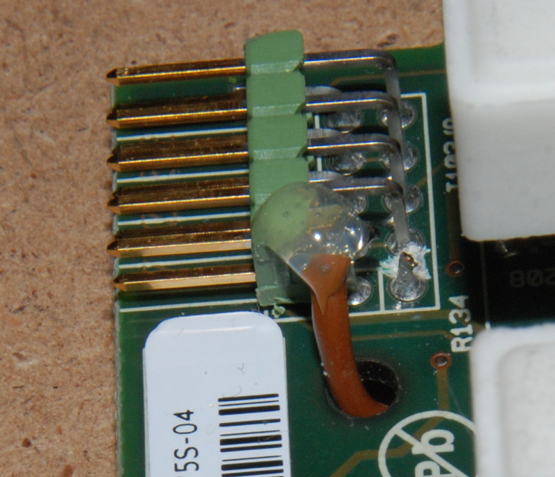
G2 kill: brown is the G2 kill line connected to Q100, blue is ground. It is not required to have that ground wire, and since additional connections may cause ground loops or currents to flow where you don't want them it may or may not a improvement to have ground wires. In this case it is just fine.
Notice the black heat shrink tubing on the brown wire, this is where the diode is inserted. I just wanted to avoid soldering the diode wire to the board, a flexible wire is much nicer. If this connection fails spot burn may result.
| Description: |
|
| Filesize: |
174.52 KB |
| Viewed: |
9546 Time(s) |
|
| Description: |
|
| Filesize: |
24.32 KB |
| Viewed: |
9546 Time(s) |
|
|
|
| Back to top |
|
|
the dude
Joined: 11 Sep 2013
Posts: 179
|
| Posted: Mon Feb 22, 2016 9:25 pm Post subject: |
|
|
The new instelled G2 kill connector on the G2 board. The yellow wire is the security loop mentionend before. Without this connector the filament voltage will be absent to prevent powering up the tubes without sufficient spot suppression.
| Description: |
|
| Filesize: |
89.5 KB |
| Viewed: |
9544 Time(s) |
|
|
|
| Back to top |
|
|
the dude
Joined: 11 Sep 2013
Posts: 179
|
| Posted: Mon Feb 22, 2016 9:27 pm Post subject: |
|
|
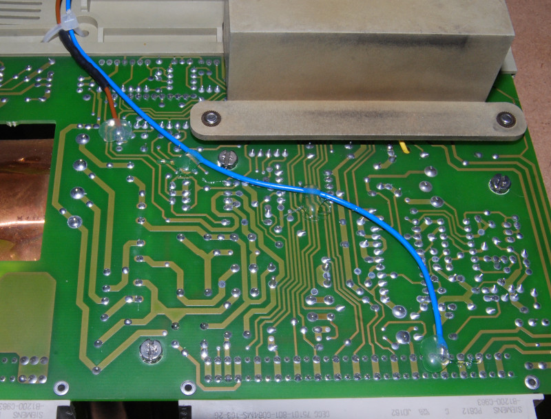
This is how i wired up the G2 balancing resistors. Be aware of proper distances to prevent arcing.
| Description: |
|
| Filesize: |
163.45 KB |
| Viewed: |
9543 Time(s) |
|
|
|
| Back to top |
|
|
the dude
Joined: 11 Sep 2013
Posts: 179
|
| Posted: Mon Feb 22, 2016 9:28 pm Post subject: |
|
|
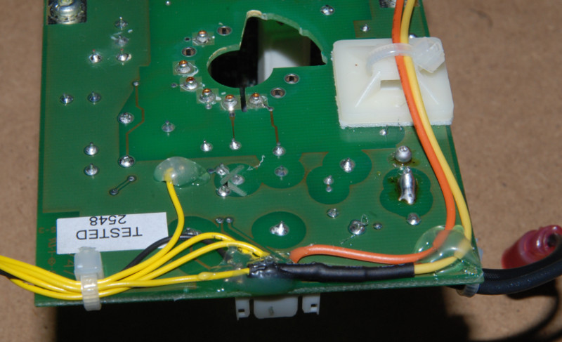
G2 kill wires on neckboard. Yellow and orange are the filament security loop, black is ground and brown is G2 kill. I used a dremel to remove carefully cut one of the ground pins (there are enough of them, and the heatsink provides ground to). Once the pin is free (double check for shorts!!) the G2 kill signal is connected there. This allows all wires go straight to the socket board, so the amp board can be removed without soldering.
You may solder the G2 kill directly on the amp board of course, you may omit the security loop, this is just how i did it.
| Description: |
|
| Filesize: |
80.41 KB |
| Viewed: |
9540 Time(s) |
|
|
|
| Back to top |
|
|
the dude
Joined: 11 Sep 2013
Posts: 179
|
| Posted: Mon Feb 22, 2016 9:30 pm Post subject: |
|
|
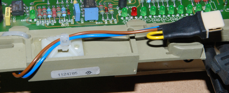
Neckboard wires for frame connection. This wire harness is reused from the 1209s board. The yellow security loop wire is connected to FIL- and the orange one is connected to the board FIL- connector. Be sure to have proper isolation distance on the small connector. Hot glue is always a great thing, and here it also helps to prevent arcing.
| Description: |
|
| Filesize: |
96.63 KB |
| Viewed: |
9538 Time(s) |
|
|
|
| Back to top |
|
|
the dude
Joined: 11 Sep 2013
Posts: 179
|
| Posted: Mon Feb 22, 2016 9:31 pm Post subject: |
|
|
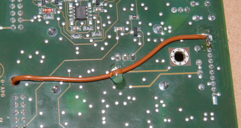
Amp board G2 kill wire. Other end is connected to the board connector.
| Description: |
|
| Filesize: |
121.6 KB |
| Viewed: |
9537 Time(s) |
|
|
|
| Back to top |
|
|
the dude
Joined: 11 Sep 2013
Posts: 179
|
| Posted: Mon Feb 22, 2016 9:31 pm Post subject: |
|
|
Amp board connector with attached G2 kill wire. The scratches are an attempt to cut the ground connection, but the pin is connected to the ground plane inside the board. So i just cut the wire.
| Description: |
|
| Filesize: |
142.45 KB |
| Viewed: |
9536 Time(s) |
|
|
|
| Back to top |
|
|
the dude
Joined: 11 Sep 2013
Posts: 179
|
| Posted: Mon Feb 22, 2016 9:33 pm Post subject: |
|
|
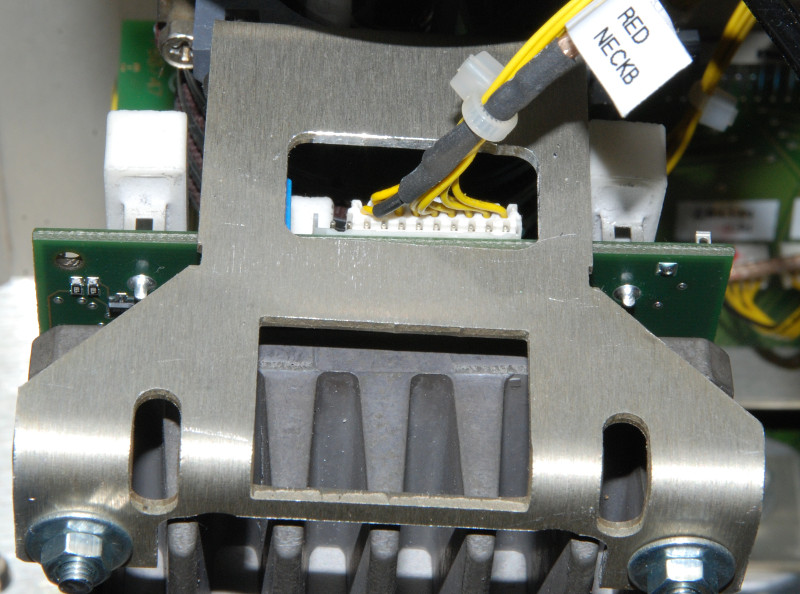
A closer view of the modified bracket with the connector in place. Notice the correct placement, the pins left beneath the video cable are ground and G2 kill (left outer pin).
| Description: |
|
| Filesize: |
129.24 KB |
| Viewed: |
9535 Time(s) |
|
|
|
| Back to top |
|
|
the dude
Joined: 11 Sep 2013
Posts: 179
|
| Posted: Mon Feb 22, 2016 9:34 pm Post subject: |
|
|
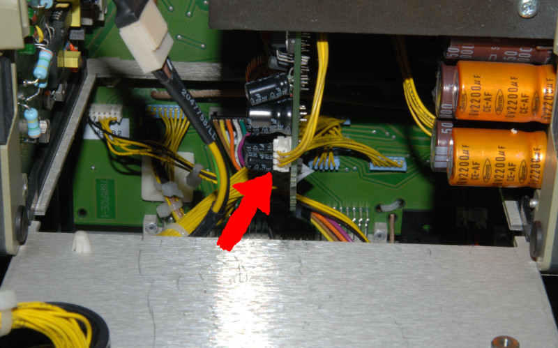
The last resort: If something goes terrible wrong and your tubes lights up bright this connector on the SMPS can be pulled in order to cut filament voltage. It takes about 30 sek. for the filaments to cool down and stop emitting. But for sure this is not the best way to power down CRT.
| Description: |
|
| Filesize: |
124.99 KB |
| Viewed: |
9534 Time(s) |
|
|
|
| Back to top |
|
|
the dude
Joined: 11 Sep 2013
Posts: 179
|
| Posted: Mon Feb 22, 2016 9:34 pm Post subject: |
|
|
You may notice the tubes light up once at startup. This is normal. When the filaments are cold the G2 voltage is already build up at at max, because there is no beam. When the beam apears the ABL kicks in and regulates down G2. This takes 1-2 secounds. Maybe the 909 starts the G2 inverter a little later. Nothing to worry about.
And the final disclaimer: Test with old tubes... Dont get electrocuted... And Have fun!
|
|
| Back to top |
|
|
barclay66
Joined: 27 Jun 2011
Posts: 1304
Location: Germany
TV/Projector: Marquee 9500 Ultra
|
| Posted: Mon Feb 22, 2016 10:45 pm Post subject: |
|
|
|
Excellent write up. Nice work!!!
|
|
| Back to top |
|
|
redfox001

Joined: 16 Mar 2009
Posts: 2257
Location: The Netherlands
|
| Posted: Mon Feb 22, 2016 10:58 pm Post subject: |
|
|
Super work! On the 909 the tubes light up at startup too.
_________________
701s->runco933->8500ultra->cinemax->9500mp->919 splitpack + cinemax
|
|
| Back to top |
|
|
the dude
Joined: 11 Sep 2013
Posts: 179
|
| Posted: Mon Feb 22, 2016 10:59 pm Post subject: |
|
|
Thanks 
|
|
| Back to top |
|
|
km987654

Joined: 25 Jul 2007
Posts: 2874
Location: Australia
TV/Projector: Barco BG809s
|
| Posted: Mon Feb 22, 2016 11:16 pm Post subject: |
|
|
Thanks as well 
|
|
| Back to top |
|
|
|
|


