| Author |
Message |
zxh398

Joined: 05 Nov 2009
Posts: 55
Location: china guangzhou
|
| Posted: Fri Jun 14, 2013 8:59 am Post subject: barco crt sockets board Replace VPA15.18 |
|
|
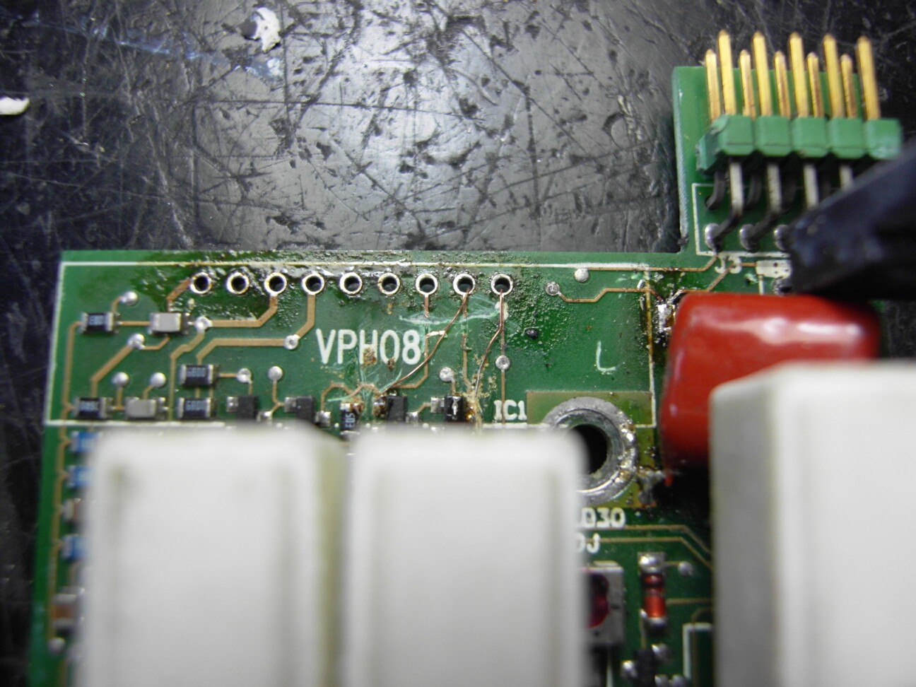
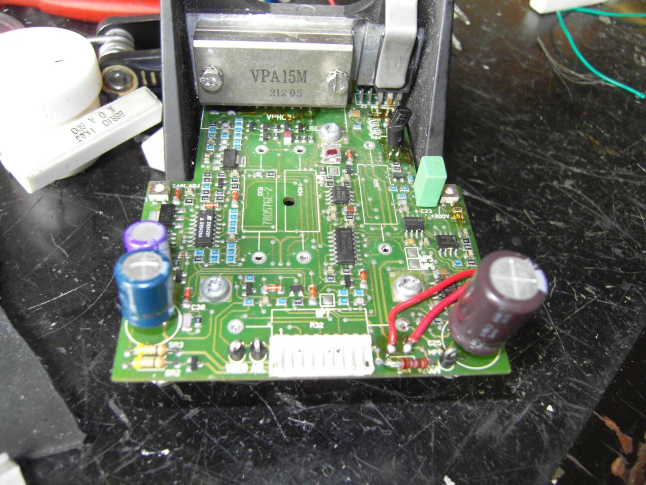
Barco barco crt sockets board Using VPH08, insufficient bandwidth of the IC,Replace the VPA15 bandwidth 150MHZ or 180MHZ or 250MHZ's VPA25 of VPA18
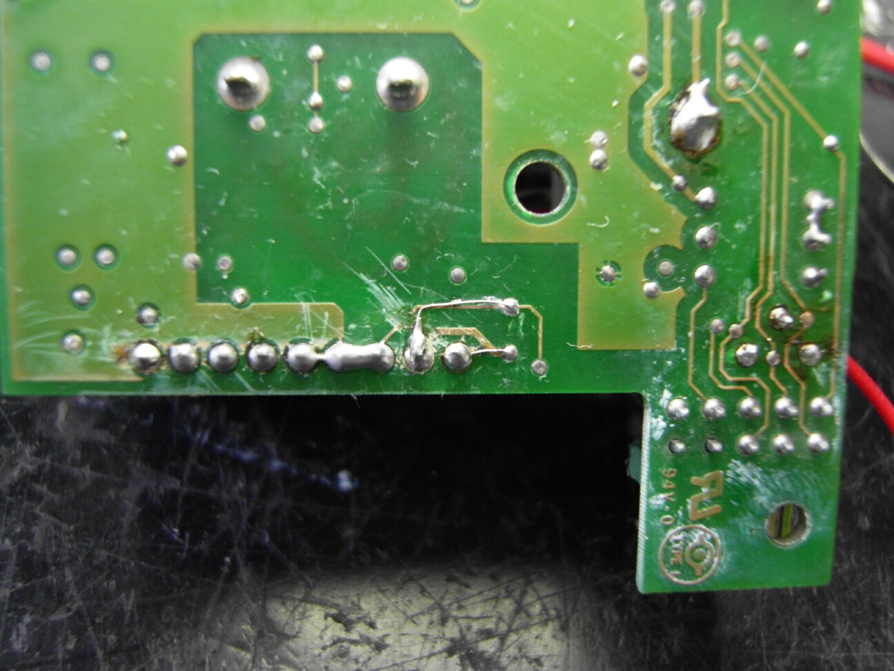
First, before the change to understand the difference between direct VPH08 and VPA15 first pin differentiated VPH08 7 feet 9 feet is a constant current output pin is connected to the supply voltage 8. VPA13.15.18.25 ground is 7 feet 8 feet 9 feet then the power output. So to change the pin order, the original plate 789 Tiaoduan 7 Ground 8 changes to the original seven positions 9 and 8 are connected. Specific methods see picture
| Description: |
|
| Filesize: |
236.7 KB |
| Viewed: |
5791 Time(s) |
|
| Description: |
| The original plate 789 Tiaoduan 7 Ground 8 changes to the original seven positions 9 and 8 are connected |
|
| Filesize: |
221.26 KB |
| Viewed: |
5791 Time(s) |
|
| Description: |
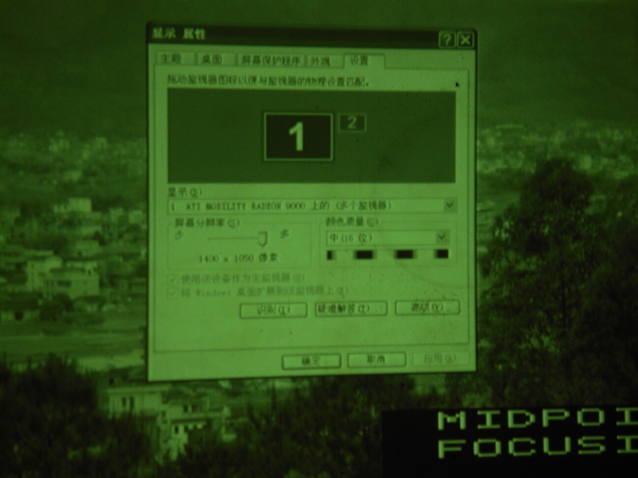
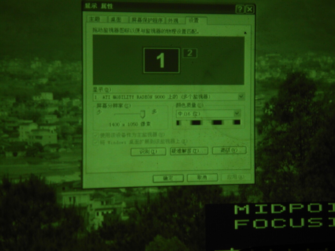
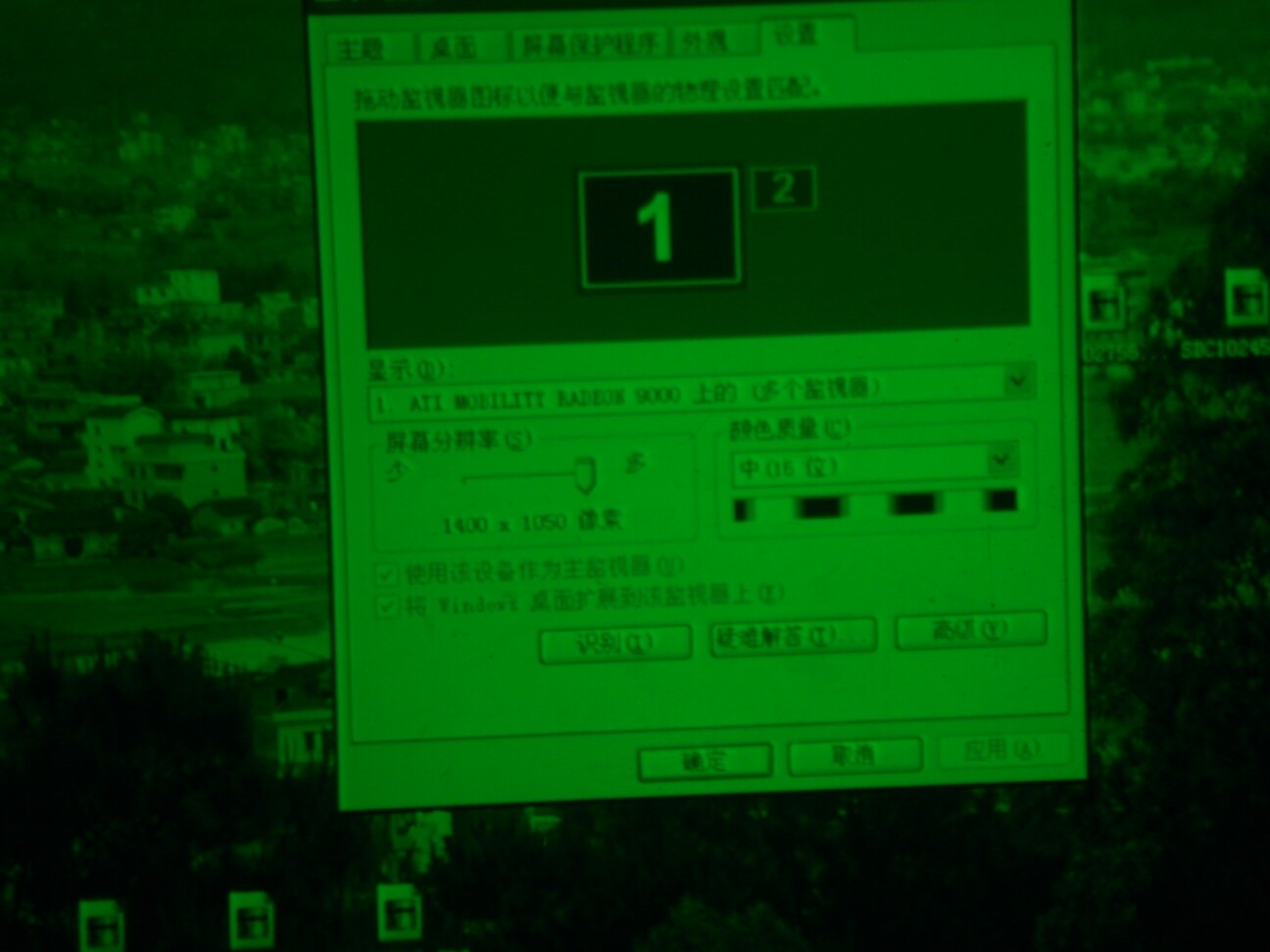
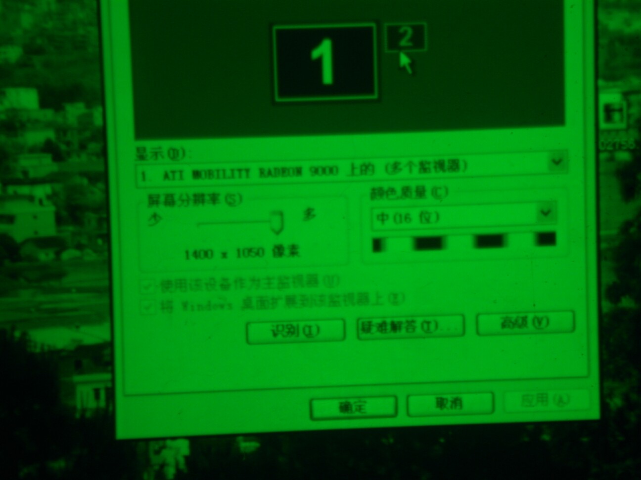
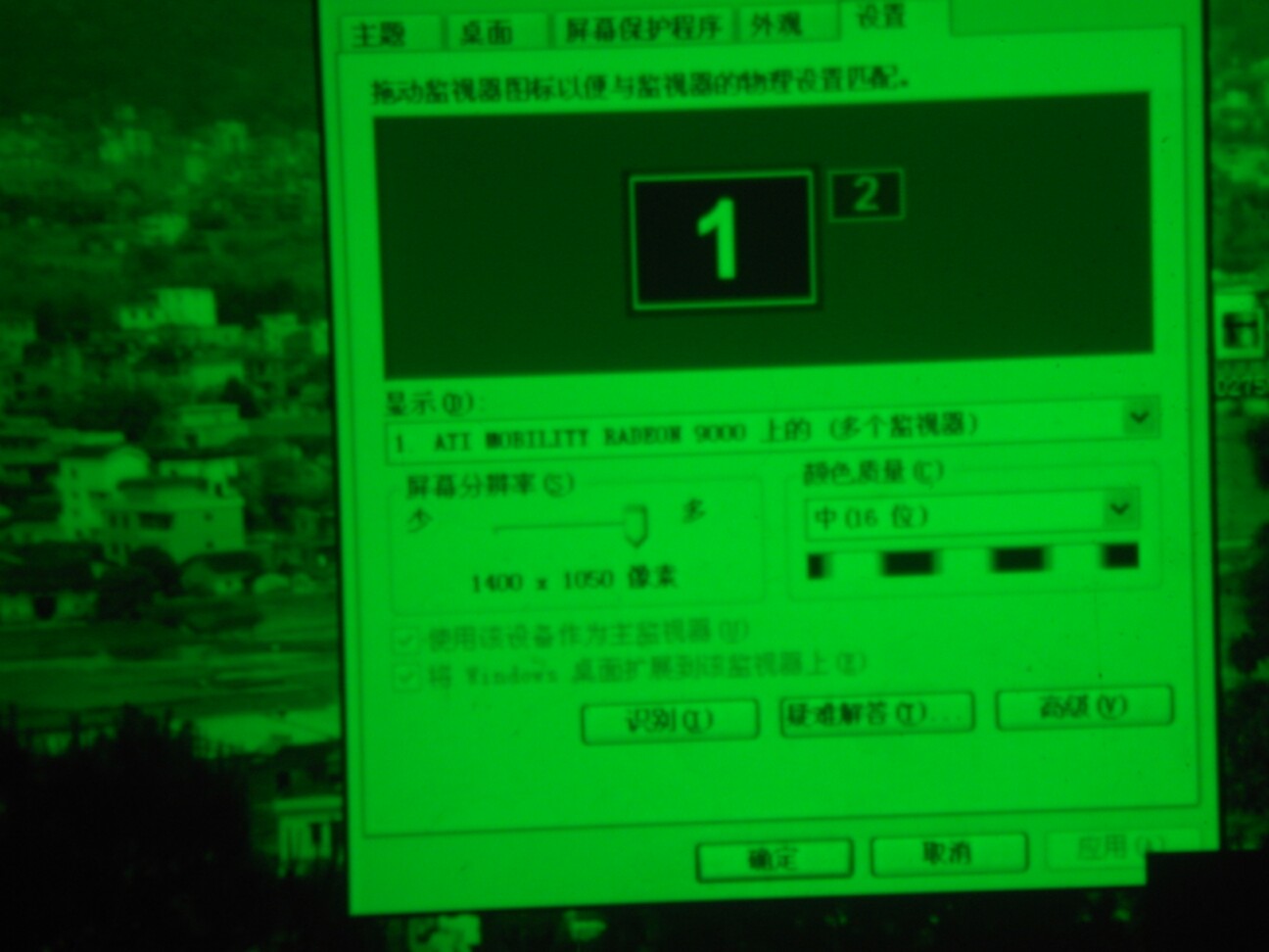
| Mainly to see the changes in the resolution of the word G2 adjustment, so I do not go to the reference dark detail and brightness |
|
| Filesize: |
150.04 KB |
| Viewed: |
5791 Time(s) |
|
| Description: |
|
| Filesize: |
150.17 KB |
| Viewed: |
5791 Time(s) |
|
| Description: |
|
| Filesize: |
121.83 KB |
| Viewed: |
5791 Time(s) |
|
| Description: |
|
| Filesize: |
119.47 KB |
| Viewed: |
5791 Time(s) |
|
| Description: |
|
| Filesize: |
129.27 KB |
| Viewed: |
5791 Time(s) |
|
| Description: |
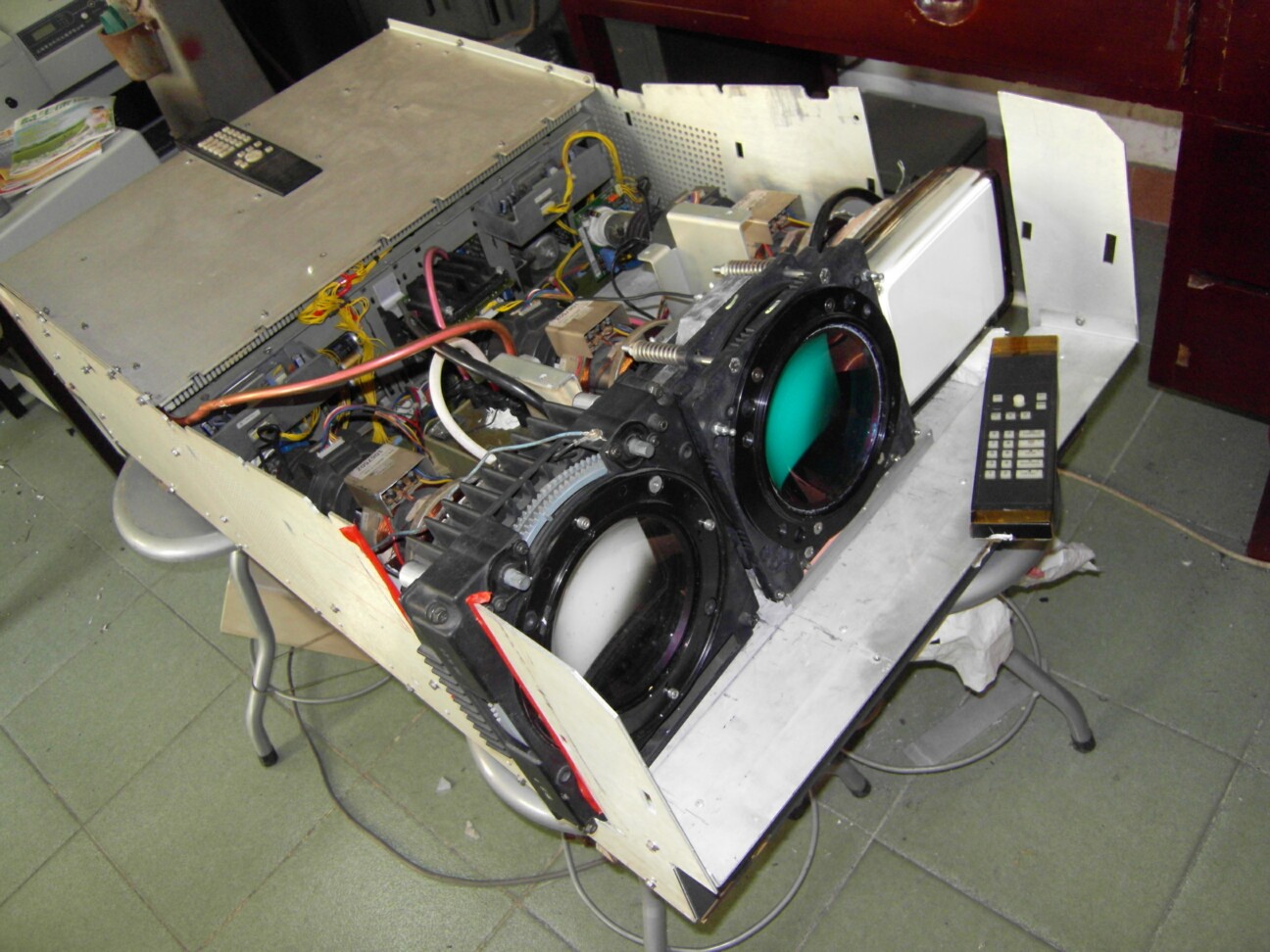
| 808S used for testing the lens with P19LCP07 + HD10 |
|
| Filesize: |
255.16 KB |
| Viewed: |
5791 Time(s) |
|
_________________
zxh1353@hotmail.com
|
|
| Back to top |
|
 |
zxh398
Joined: 05 Nov 2009
Posts: 55
Location: china guangzhou
|
| Posted: Fri Jun 14, 2013 9:12 am Post subject: |
|
|
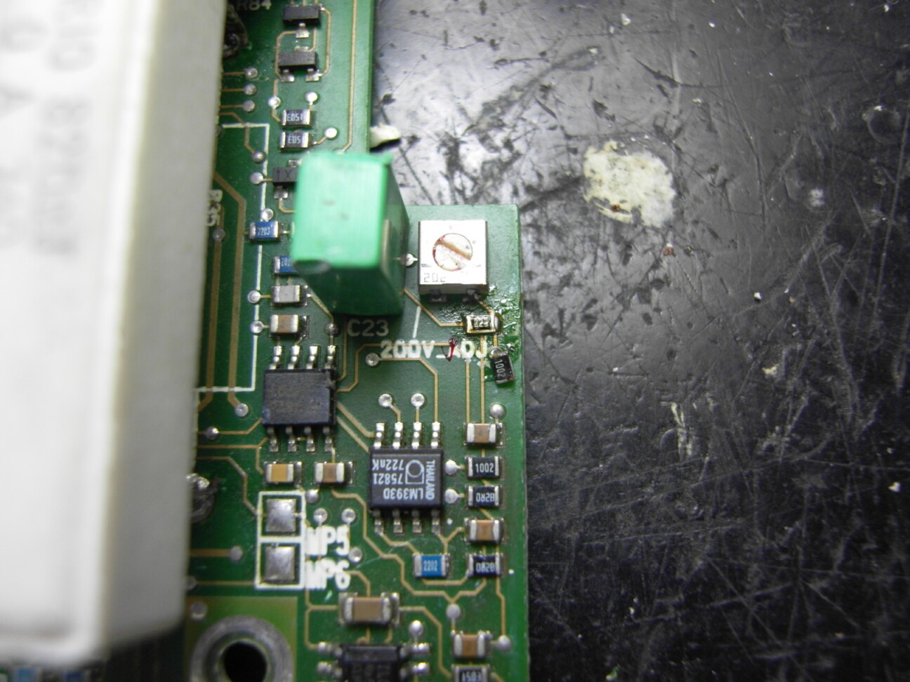
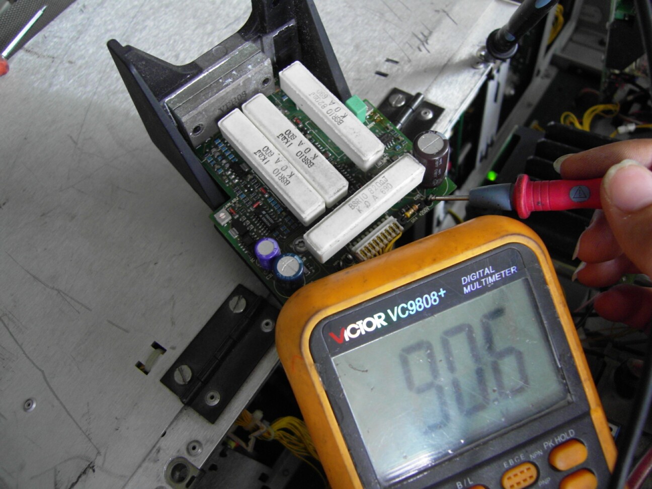
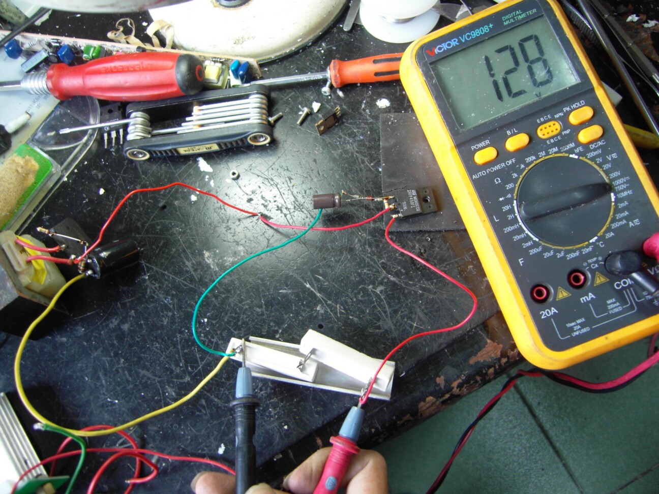
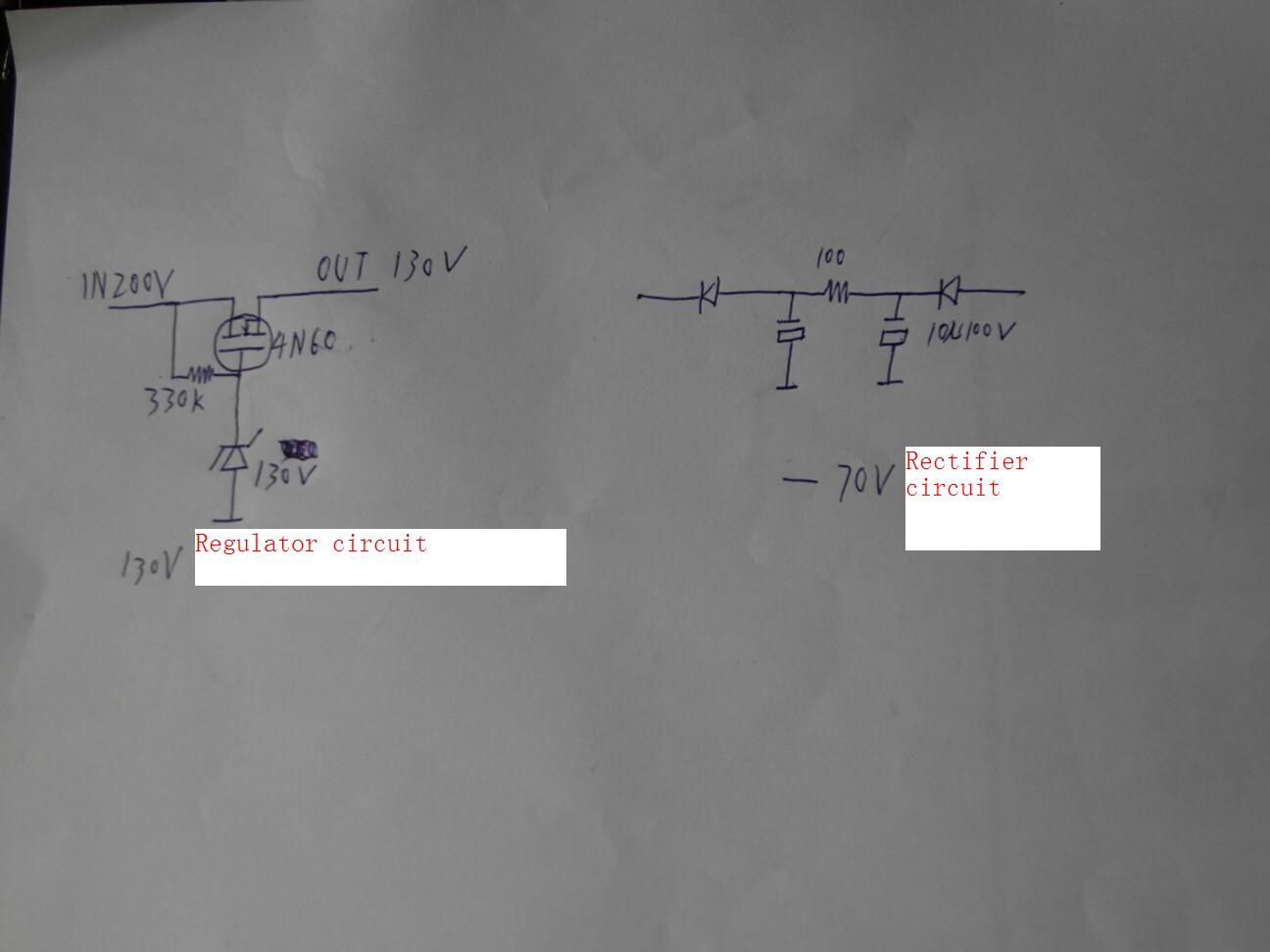
VPH08 and VPA15 there is a big difference between the input voltage is different, VPH08 is connected to 200V voltage is 90V voltage VPA15 Barco S tail board has a voltage regulator circuit 200V-ADJ potentiometer near obtain VPA15 need to change the required 90V voltage. First, modify the circuit board R92 resistor value, this adjustment potentiometer resistor 200V side is easy to find, is a 1002 chip resistor is 10K. Replaced with a 223 chip resistors, and the original 200V potentiometer clockwise transferred obtained at the end of output voltage of 90V, but this circuit can not withstand the high voltage difference, that is, the input can easily burn 90V 200V output voltage regulation components. So I created a simple step-down circuit, using a reference picture 130V regulator and a common 4N60 FET available and a 330K resistor, capacitor can do without it is just to make the output voltage ripple is smaller settings.
| Description: |
| Replacement Chip Resistor location |
|
| Filesize: |
228.99 KB |
| Viewed: |
5788 Time(s) |
|
| Description: |
| IC supply voltage test points |
|
| Filesize: |
236.34 KB |
| Viewed: |
5788 Time(s) |
|
| Description: |
| 130V regulator circuit test |
|
| Filesize: |
331.87 KB |
| Viewed: |
5788 Time(s) |
|
| Description: |
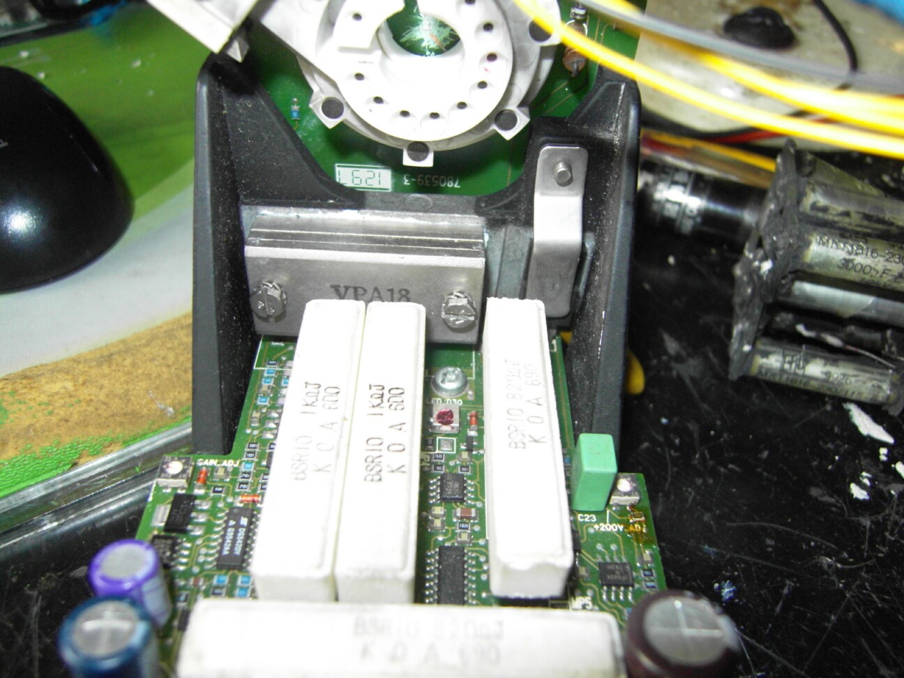
| The method is the same installation VPA18 |
|
| Filesize: |
244.83 KB |
| Viewed: |
5788 Time(s) |
|
| Description: |
| Regulator circuit access point |
|
| Filesize: |
298.53 KB |
| Viewed: |
5788 Time(s) |
|
| Description: |
|
| Filesize: |
274.07 KB |
| Viewed: |
5788 Time(s) |
|
_________________
zxh1353@hotmail.com
|
|
| Back to top |
|
|
zxh398
Joined: 05 Nov 2009
Posts: 55
Location: china guangzhou
|
| Posted: Fri Jun 14, 2013 9:32 am Post subject: |
|
|
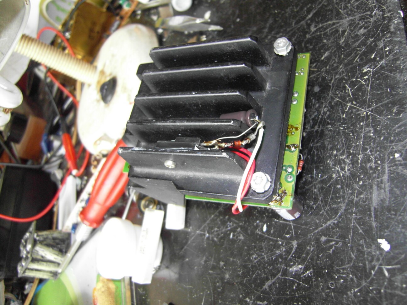
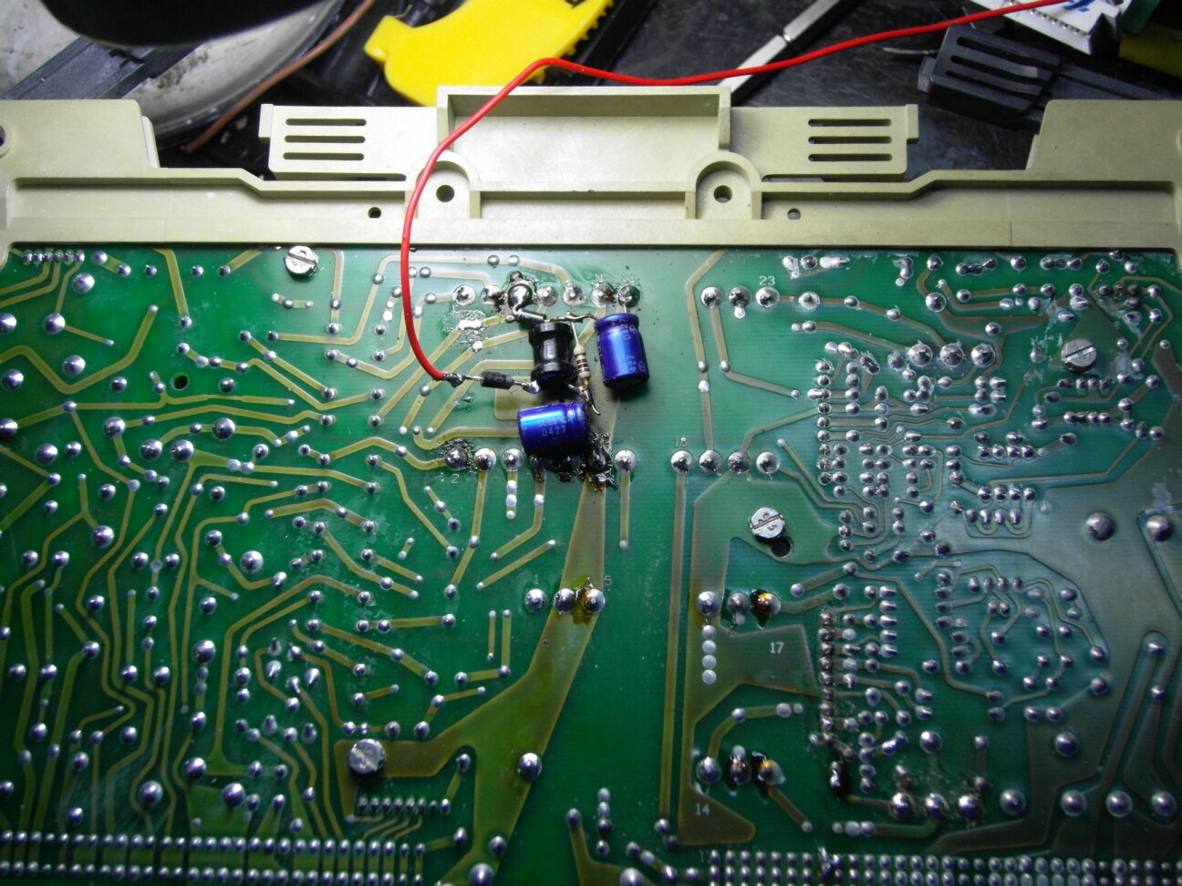
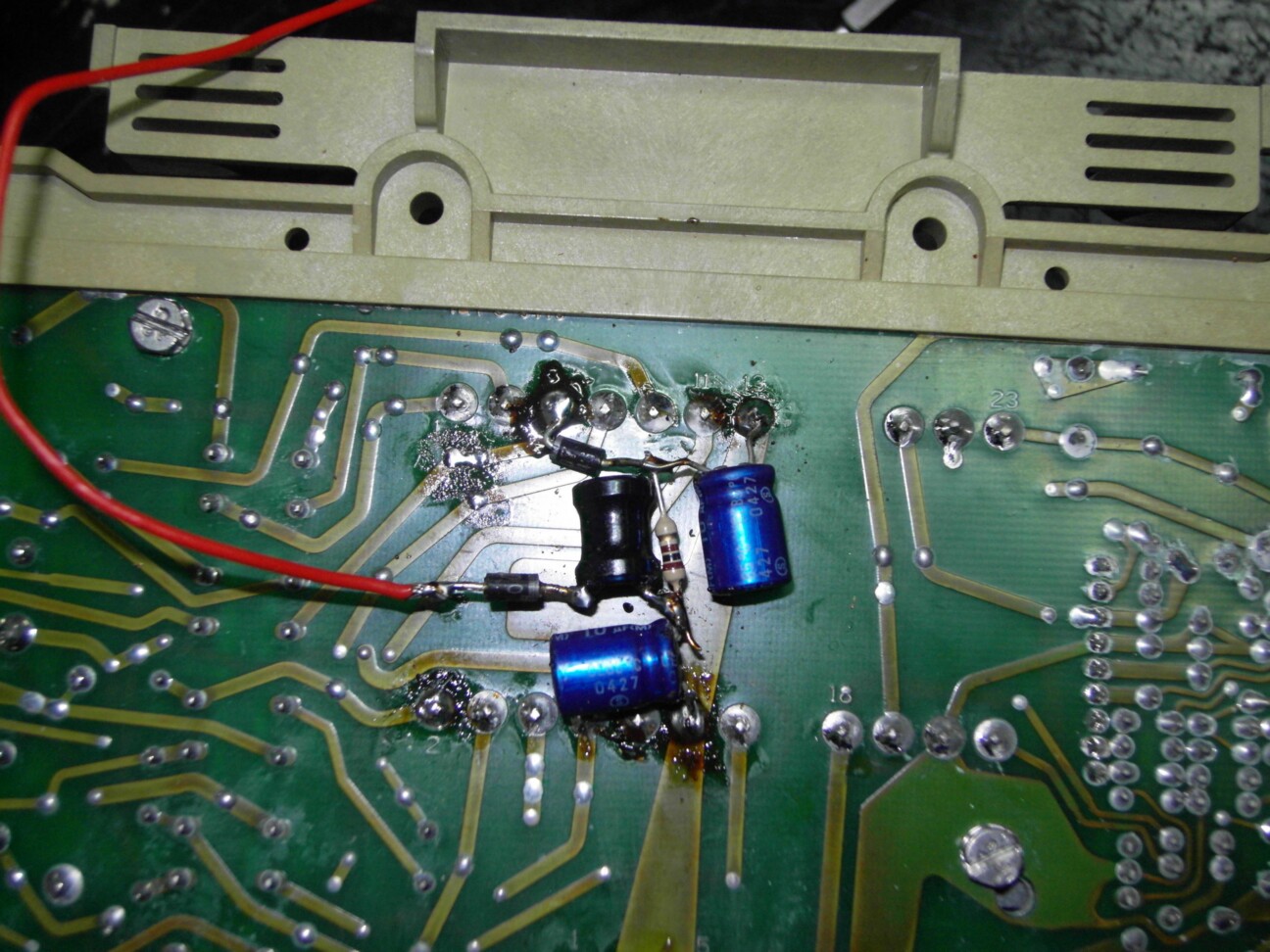
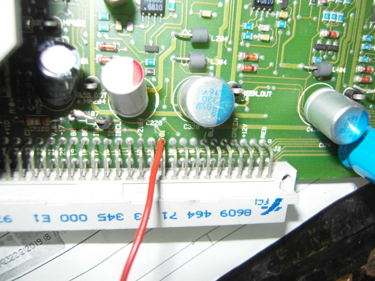
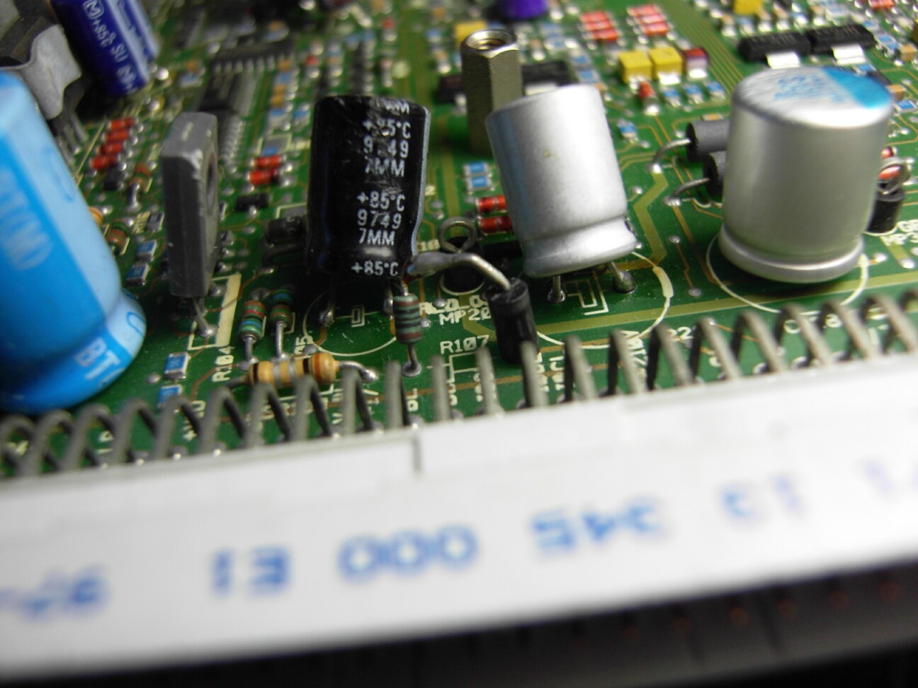
Normal test machine after installation, but the lower half of the electricity VPA15 k resulting voltage is too low. The whole picture becomes very bright bottom ash can not be extinguished, the cathode voltage is too low will cause the image brightness at the trailing issue. This problem is solved in order to achieve practical state of the machine, in fact, to provide an approximately-70V G1 voltage can solve this problem. First find the location of the power 30V rectifier circuit a simple one-way diode and capacitor Jieshangqu you can get more negative about 70V, I use a filter can make DC more pure. G1 requires little current, no special requirements just diode switching power supply for the job if the recommended RF4007. Connected with a line connected to the rear side of the G1 input board feet, in order not to affect the G1 shutdown circuit must eliminate highlights position in the R107 series with a diode. As long as this is the rectifying diode can be, must not mistake the other polarity is not required.
| Description: |
| Modify the position of the power board |
|
| Filesize: |
307.82 KB |
| Viewed: |
5780 Time(s) |
|
| Description: |
| Modify the position of the power board |
|
| Filesize: |
283.42 KB |
| Viewed: |
5780 Time(s) |
|
| Description: |
| The position of the access-70V R762720 |
|
| Filesize: |
261.38 KB |
| Viewed: |
5780 Time(s) |
|
| Description: |
| Intrusion prevention-70V diode |
|
| Filesize: |
194.54 KB |
| Viewed: |
5780 Time(s) |
|
| Description: |
|
| Filesize: |
52.06 KB |
| Viewed: |
5780 Time(s) |
|
_________________
zxh1353@hotmail.com
|
|
| Back to top |
|
|
gjaky
Joined: 05 Jun 2010
Posts: 2802
Location: Budapest, Hungary
|
| Posted: Fri Jun 14, 2013 9:44 am Post subject: |
|
|
Very interesting, I myself working on NEC PG xtra modification, I replaced the VPA13s with VPA15H (found in sony 1292, G70) the VPA15H can stand 110Vcc at least -while the plain VPA15 only stands 90Vcc, what about the VPA15M you use, where they came from?
Currently I'm stuck with my modifications because tuning in (peaking) the neck board would require some heavy measuring equipmnets, however the barco neckboard is somewhat simplier than the NEC as barco only have RC components for peaking. Without adjusting the peaking you can get lower overall bandwidth, or ringing (I can see some unwanted ringing on the VPA15 pictures above)
_________________
projectors in the past : NEC 6-9PG xtra, Electrohome Marquee 6-7500, NEC XG 1351 LC ( with super modified Electrohome VNB neckboard !!!)
current: VDC Marquee 9500LC
The MOD: VNB-DB, VIM-DB
|
|
| Back to top |
|
|
zxh398
Joined: 05 Nov 2009
Posts: 55
Location: china guangzhou
|
| Posted: Fri Jun 14, 2013 10:02 am Post subject: |
|
|
If the NEC replacement VPA15.18.25 90V regulator series with the regulator circuit can be achieved
_________________
zxh1353@hotmail.com
|
|
| Back to top |
|
|
gjaky
Joined: 05 Jun 2010
Posts: 2802
Location: Budapest, Hungary
|
| Posted: Fri Jun 14, 2013 10:14 am Post subject: |
|
|
Yes, but then I may run out of G2 range (further modifications would be needed) with this it is plug and play. On the other hand my VPA15 neck board don't perform any better (so far) than the original.
_________________
projectors in the past : NEC 6-9PG xtra, Electrohome Marquee 6-7500, NEC XG 1351 LC ( with super modified Electrohome VNB neckboard !!!)
current: VDC Marquee 9500LC
The MOD: VNB-DB, VIM-DB
|
|
| Back to top |
|
|
zxh398
Joined: 05 Nov 2009
Posts: 55
Location: china guangzhou
|
| Posted: Fri Jun 14, 2013 10:26 am Post subject: |
|
|
VPA13 direct replacement VPA15 Maybe, after all voltage approaches. But will bring the risk of burn IC, IC burn off may cause the phosphor burn bright
_________________
zxh1353@hotmail.com
|
|
| Back to top |
|
|
zxh398
Joined: 05 Nov 2009
Posts: 55
Location: china guangzhou
|
| Posted: Fri Jun 14, 2013 12:36 pm Post subject: |
|
|
G2 after power needs to be adjusted slightly. I tried a few days without any problems very stable machine, change the end of this tail board feel the difference is not great. Might have been previously input board bandwidth limitations, VPA15 and 18 is not much difference. Fonts clear a little bit, and there are trim issue. Flanger is overcompensated cause, that had enough 120MHZ bandwidth video channel factory for a high-frequency boost. For the IC to see more clearly.
_________________
zxh1353@hotmail.com
|
|
| Back to top |
|
|
SisterOfMercy

Joined: 31 Oct 2007
Posts: 155
Location: Zwart Nazareth, The Netherlands
|
| Posted: Sat Jun 15, 2013 5:10 pm Post subject: |
|
|
| zxh398 wrote: | | Flanger is overcompensated cause, that had enough 120MHZ bandwidth video channel factory for a high-frequency boost. For the IC to see more clearly. |
Is that the trick Barco used to get 120 MHz bandwidth out of VPH08 chips?
_________________
The kissing and the colour come crashing down
|
|
| Back to top |
|
|
zxh398
Joined: 05 Nov 2009
Posts: 55
Location: china guangzhou
|
| Posted: Mon Jun 17, 2013 3:35 am Post subject: |
|
|
Chrome is the RC circuit caused, RC is to compensate high-frequency signal fall
_________________
zxh1353@hotmail.com
|
|
| Back to top |
|
|
wwm
Joined: 15 Aug 2012
Posts: 18
|
| Posted: Fri Jun 21, 2013 2:52 am Post subject: |
|
|
Support zxh398, I was wwm1208.
Players in the CRT projector, it seems yet to see someone make such a modification.
You can further attempts to modify Buck's video channel.
|
|
| Back to top |
|
|
|
|