| Author |
Message |
Jeremy112
Joined: 28 Sep 2006
Posts: 2649
Location: Fond du Lac, WI
|
| Posted: Thu May 24, 2012 8:23 pm Post subject: Denon AVR-2307CI - Turns on then goes into protection |
|
|
Soooooo, Mac, if you're around and just happen to see yourself reading this post, or to anyone else.... I have a Denon AVR-2307CI here that turns on, appears to work, then shuts down into protection mode a couple seconds later.
From what I have read online, it is a problem with the power amplifier section, however, since I have been unable to find a service manual for free of any kind anywhere, I don't know...
I know your probably busy mac, and I know you have a couple items of mine already:P but this I think is something I can fix, its easy to get into and its 70lbs lighter 
I guess what I'm looking for is confirmation of the actual problem. as said its rumored that the ouput chips blow on this unit, and that its a common problem. I must say though, nothing smells burnt and without taking it all the way apart, it looks fine.
So mac if you, or anyone else is not busy and wants to take a shot at this, I'd appreciate it, this shouldn't be more than a 1 day project:P
_________________
When I'm asking for a Model number, that doesn't mean I'm asking for a nude photo with your number on it 
|
|
| Back to top |
|
 |
macgyver655
Joined: 22 Aug 2007
Posts: 8508
|
| Posted: Thu May 24, 2012 9:52 pm Post subject: |
|
|
|
Give me an hour or so and I'll look into it. Unless someone else offers something before then.
|
|
| Back to top |
|
|
macgyver655
Joined: 22 Aug 2007
Posts: 8508
|
| Posted: Thu May 24, 2012 10:47 pm Post subject: |
|
|
|
Does it go into protect right after you hear the speaker relays click? Or is it on for a little bit after they click?
|
|
| Back to top |
|
|
Curt Palme
CRT Tech
Joined: 08 Mar 2006
Posts: 24396
Location: Langley, BC
TV/Projector: All of them!
|
| Posted: Thu May 24, 2012 11:44 pm Post subject: |
|
|
I have an older model apart here on the bench, but the diagnosis is probably the same... mine had a blown channel.
If you have output transistors other than output chips, just measure each channel for shorts on the main outputs. Usually, if you find shorted outputs and remove them from the circuit, the other channels will work fine. In my case, the drivers to the outputs were on little modules that unsoldered, so I removed the blown center channel and the receiver worked fine.
|
|
| Back to top |
|
|
Jeremy112
Joined: 28 Sep 2006
Posts: 2649
Location: Fond du Lac, WI
|
| Posted: Thu May 24, 2012 11:59 pm Post subject: |
|
|
| macgyver655 wrote: | | Does it go into protect right after you hear the speaker relays click? Or is it on for a little bit after they click? |
Mac,
Its a little bit after they click, the display is lit, and right before it turns off I am able to adjust the functions/volume etc...
_________________
When I'm asking for a Model number, that doesn't mean I'm asking for a nude photo with your number on it
|
|
| Back to top |
|
|
macgyver655
Joined: 22 Aug 2007
Posts: 8508
|
| Posted: Fri May 25, 2012 12:21 am Post subject: |
|
|
|
Well you can try what Curt says or since it stays on for a little you can connect your volt meter to the speaker terminals 1 at a time and see if there is any voltage when the relays latch.
|
|
| Back to top |
|
|
Jeremy112
Joined: 28 Sep 2006
Posts: 2649
Location: Fond du Lac, WI
|
| Posted: Fri May 25, 2012 1:10 am Post subject: |
|
|
| macgyver655 wrote: | | Well you can try what Curt says or since it stays on for a little you can connect your volt meter to the speaker terminals 1 at a time and see if there is any voltage when the relays latch. |
I tested each speaker output for vdc and millivolts dc, nothing on any of them, ill try it curts way and see what happens
_________________
When I'm asking for a Model number, that doesn't mean I'm asking for a nude photo with your number on it
|
|
| Back to top |
|
|
macgyver655
Joined: 22 Aug 2007
Posts: 8508
|
| Posted: Fri May 25, 2012 1:16 am Post subject: |
|
|
|
You can also try disconnecting CP103 on the main board and see if it stays on. You wont have any sound output but we need to find out whats kicking the protect mode. I'll be back tomorrow.
|
|
| Back to top |
|
|
Jeremy112
Joined: 28 Sep 2006
Posts: 2649
Location: Fond du Lac, WI
|
| Posted: Fri May 25, 2012 1:25 pm Post subject: |
|
|
| macgyver655 wrote: | | You can also try disconnecting CP103 on the main board and see if it stays on. You wont have any sound output but we need to find out whats kicking the protect mode. I'll be back tomorrow. |
I tried disconnecting CP103 but it still does the same thing, I haven't tried it curts way yet because I'm unsure how this one dissassembles... from the looks of it I can remove the whole thing from the chassis without disconnecting things.
_________________
When I'm asking for a Model number, that doesn't mean I'm asking for a nude photo with your number on it
|
|
| Back to top |
|
|
macgyver655
Joined: 22 Aug 2007
Posts: 8508
|
| Posted: Fri May 25, 2012 2:45 pm Post subject: |
|
|
|
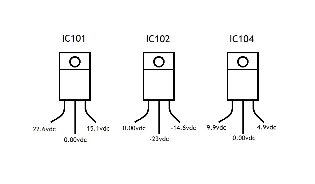
Disconnecting that connector should eliminate the output section. You will have to check the regulators on that board. IC104 = +5v, IC101 = +15v and IC102 = -15v. I'm guessing the +15v reg bad.
|
|
| Back to top |
|
|
Jeremy112
Joined: 28 Sep 2006
Posts: 2649
Location: Fond du Lac, WI
|
| Posted: Fri May 25, 2012 4:12 pm Post subject: |
|
|
| macgyver655 wrote: | | Disconnecting that connector should eliminate the output section. You will have to check the regulators on that board. IC104 = +5v, IC101 = +15v and IC102 = -15v. I'm guessing the +15v reg bad. |
Interesting, so your saying that the power supply section could be the issue and not the output chips? I'll check those ICs out and get back to you mac, thanks 
_________________
When I'm asking for a Model number, that doesn't mean I'm asking for a nude photo with your number on it
|
|
| Back to top |
|
|
Jeremy112
Joined: 28 Sep 2006
Posts: 2649
Location: Fond du Lac, WI
|
| Posted: Fri Jun 01, 2012 1:31 am Post subject: |
|
|
Mac,
Sorry it took a week to get back to this, I'm pretty busy around here and have been trying to get back to this, I finally have a few days to do so.
heres a pic I made of the ICs you told me to test, I'm not sure what pins were the E C or B so I made a visual :p
| Description: |
|
| Filesize: |
48.6 KB |
| Viewed: |
21771 Time(s) |
|
_________________
When I'm asking for a Model number, that doesn't mean I'm asking for a nude photo with your number on it
|
|
| Back to top |
|
|
Jeremy112
Joined: 28 Sep 2006
Posts: 2649
Location: Fond du Lac, WI
|
| Posted: Fri Jun 01, 2012 1:34 am Post subject: |
|
|
Also the pic is showing the chips as the fronts of the chip
_________________
When I'm asking for a Model number, that doesn't mean I'm asking for a nude photo with your number on it
|
|
| Back to top |
|
|
macgyver655
Joined: 22 Aug 2007
Posts: 8508
|
| Posted: Sat Jun 02, 2012 12:14 am Post subject: |
|
|
Those numbers look fine. Guess this one is going ot be tricky.
Go to the CPU board and locate CP3001. DMM on DC, pin 4 neg, pin 5 pos. Turn it on and tell me the voltage.
|
|
| Back to top |
|
|
Jeremy112
Joined: 28 Sep 2006
Posts: 2649
Location: Fond du Lac, WI
|
| Posted: Sun Jun 03, 2012 9:21 pm Post subject: |
|
|
| macgyver655 wrote: | Those numbers look fine. Guess this one is going ot be tricky.
Go to the CPU board and locate CP3001. DMM on DC, pin 4 neg, pin 5 pos. Turn it on and tell me the voltage. |
Mac, On pins 4 and 5 of CP3001 (I used CP3001B since it was easier to access) I get only -0.10vdc for a split second about 2 of 4 seconds into the turn on and shutdown cycle, otherwise it had no voltage while on
_________________
When I'm asking for a Model number, that doesn't mean I'm asking for a nude photo with your number on it
|
|
| Back to top |
|
|
macgyver655
Joined: 22 Aug 2007
Posts: 8508
|
| Posted: Sun Jun 03, 2012 9:56 pm Post subject: |
|
|
|
where is CP3001B?
|
|
| Back to top |
|
|
Jeremy112
Joined: 28 Sep 2006
Posts: 2649
Location: Fond du Lac, WI
|
| Posted: Sun Jun 03, 2012 10:04 pm Post subject: |
|
|
| macgyver655 wrote: | | where is CP3001B? |
From what I saw, CP3001A is on the CPU/HDMI board, and CP3001B goes to the component board (connection A goes to B of course), and I did make sure I was on the right pin numbers.
_________________
When I'm asking for a Model number, that doesn't mean I'm asking for a nude photo with your number on it
|
|
| Back to top |
|
|
Jeremy112
Joined: 28 Sep 2006
Posts: 2649
Location: Fond du Lac, WI
|
| Posted: Sun Jun 03, 2012 10:12 pm Post subject: |
|
|
Mac, I also checked the pins on CP3001A (the one you wanted me to check) and they read the same. Also.. I assume the CPU board is the HDMI board since it had CP3001. Hope I'm correct
_________________
When I'm asking for a Model number, that doesn't mean I'm asking for a nude photo with your number on it
|
|
| Back to top |
|
|
macgyver655
Joined: 22 Aug 2007
Posts: 8508
|
| Posted: Sun Jun 03, 2012 10:14 pm Post subject: |
|
|
I'm not seeing that connector number and I dont have time to look for it. I'm on my way out. The pins I gave you should of had +5v on it.
Lets try it this way. On the CPU board look for diode D203. DMM on DC and neg leed connected to CP553, pin 4. With the pos leed you should have +5v on 1 side of the diode and +5.6v on the other side. Let me know what you get. I'll check back in an hour.
|
|
| Back to top |
|
|
macgyver655
Joined: 22 Aug 2007
Posts: 8508
|
| Posted: Sun Jun 03, 2012 10:16 pm Post subject: |
|
|
|
The CPU board has IC202 (M30626) on it.
|
|
| Back to top |
|
|
|
|


