|
As this forum is rarely used anymore, we've locked it. Feel free to browse and read. Questions? Please reach out to us directly. Cheers! |

|
 |
|
|
| Author |
Message |
gjaky
Joined: 05 Jun 2010
Posts: 2802
Location: Budapest, Hungary
|
| Posted: Wed Mar 23, 2011 1:33 pm Post subject: NEC PG deflection board experiment |
|
|
|
I have some plain PG deflection boards, and one of them (72137094) uses a very similar PCB to PG xtra PCB. I want to turn the plain PG deflection board to a PG xtra. I am currently checking the component values and positions, of course there are some (minor) differences, unfortunately on the PCB itself too. Could someone supply me the schematic of the plain PG deflection board to check the wirings too?
|
|
| Back to top |
|
 |
gjaky
Joined: 05 Jun 2010
Posts: 2802
Location: Budapest, Hungary
|
| Posted: Tue Apr 05, 2011 1:04 pm Post subject: |
|
|
It turned out that the xxx94 board is from a PG PLUS, not a plain PG...
Otherwise I have finished the conversion, and seems to be working, so if anyone is interested how to do this I have part comparision list and 'to do' list.
I also figured out that only the IC5001 determines that the board is for 6PG or 9PG. in a 6PG the ic called FVA, in the 9PG called FVB.
|
|
| Back to top |
|
|
Elaine Benes
Joined: 25 Apr 2006
Posts: 1416
|
| Posted: Wed Apr 06, 2011 2:56 am Post subject: |
|
|
|
Great work ! Congratulations.
|
|
| Back to top |
|
|
grogthegreat
Joined: 16 May 2007
Posts: 166
Location: San Diego, CA
|
| Posted: Wed Apr 06, 2011 3:23 am Post subject: |
|
|
Please post! This is great info. These boards fail often and sometimes it is hard to find a replacement from the exact same PG version.
_________________
First projector: Sony 1252q with 3500 hours
Second projector: NEC 9PG+
current projector: Sony G90
100" 3:4 draper screen.
I must keep upgrading till the voices stop!!
"I CAN HAZ CRT PRUJEKTER."
-Curt Palme
|
|
| Back to top |
|
|
gjaky
Joined: 05 Jun 2010
Posts: 2802
Location: Budapest, Hungary
|
| Posted: Wed Apr 06, 2011 7:06 am Post subject: |
|
|
just for sure:
*************************************************************************************
ABSOLUTELY NO WARRANTY
BE VERY CAREFUL DURING THE OPERATION. IF YOU DON'T KNOW EXACTLY WHAT TO DO, DON'T DO!
*************************************************************************************
In every case you will need a bad PG xtra deflection board, because the "V-posi" and "H-wave" daughterboards are unique for this model... This procedure only can be done using a 72137094 board to convert it to a 72137096. The 72137091 differs from these too much, but the main parts are the same.
http://users.hszk.bme.hu/~jg695/ here you can find the part list and some pictures how I did things.
The vertical section is a straightforward, nothing special to do.
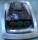
I have seen two different kind of PG xtra def board (a 6 and a 9) on the 9PG xtra board there is the additional resistor, but on the 6PG xtra's board there was no additional resistor. The picture will help how it is oriented.
It is not a bad idea to reacap the board as well
The horizontal section is harder, there are some added components, but there is no place for them, so you have to tweak.
For locating the parts I will use the following orientation: the board is upside down so the solder side faces to me, and the heat sink is the farthest side from me.
here are the special steps:
-transplant the two daughterboards
-solder the new R359 (3M9) between IC021 pin 5 and 7
-place a short between the right leg of the former R359 and the left leg of R360
-add the new R360 between HIC pin 6 and 5 (5 is the GND)
-add C269A between the two bases of Q214 and Q212.
-one end of the R391A is soldered to C051 (+)pole, the other end of the resistor is connected to R391's right hole.
-R361 between Q301 base and R095A's left hole
-C305A between HV pin 5 and 9 (9 is the GND)
-connect Q327A's emitter to C107's (-) pole, collector to Q372's base, Q327A's base to DP pin 2 (see pic: input section)
-place ZD372 between base and emitter of Q327A (cathode to the base)
-Q153A's emitter to R158's right leg, base: IC302's pin 7
-one end of R136A to R158's left leg, the other end of the resistor to Q153A's collector.
-Q153B's emitter to R139's left leg, base: through R136B to IC021's pin 7, collector: through R353C to the left leg of R137 (this is the same as the left leg of R158)
-C102A:one end: right leg of C102, other: to nearest pin of VR008
-on my original board the VR008 was set to 3,6kohm.
I hope I mentioned everything... If you missing something, ask!
|
|
| Back to top |
|
|
gjaky
Joined: 05 Jun 2010
Posts: 2802
Location: Budapest, Hungary
|
| Posted: Sat Apr 09, 2011 8:18 am Post subject: |
|
|
Found an other thing, which I missed before:
-connect DP pin 4 (on the main deflection board) to VP pin 4
|
|
| Back to top |
|
|
gjaky
Joined: 05 Jun 2010
Posts: 2802
Location: Budapest, Hungary
|
| Posted: Wed Apr 13, 2011 10:55 am Post subject: |
|
|
OOkaaay. It looks like I reach the end of the game. My geometry problem, which I explained in an other topic was also related to the deflection board. There was missing a resistor from my board which was signed as present in the PG plus schematic (and of course in the PG xtra sch).
Now every geometry and convergence settings are working fine, tested at 1600x1200 and 1080p.
The part list is updated, and also found a mistyping in the existing list (C(5)402 NOT 2200uf, instead 22000uf; and the missing resistor was R(4)120 which is a 100R)
|
|
| Back to top |
|
|
|
|
|
|
|
You cannot post new topics in this forum
You cannot reply to topics in this forum
You cannot edit your posts in this forum
You cannot delete your posts in this forum
You cannot vote in polls in this forum
You cannot attach files in this forum
You can download files in this forum
|
Forum powered by phpBB © phpBB Group
|
|


