| Author |
Message |
draganm

Joined: 08 Mar 2006
Posts: 8990
Location: Colorado
|
| Posted: Fri Nov 12, 2010 8:15 pm Post subject: |
|
|
| SGIforever wrote: | If I leave it turned of now for a couple of days, when wait for the electrical components to arrive, I hope there won't be to much power left in the capacitors or anywhere else.
I will need to trim the voltage before putting it into the chassis again though which means plugging it in outside the chassis.
I can't find Nashou66 mentioning which leads to measure between. Should I measure on the rail somewhere or is it the two lower leads on the picture showing the back side of the board?
|
I really wouldn't do that, especially with EU 230V power. You could get killed.
Simply unplug the P14 connector at Motherboard behind blue tube. No voltage will be going to the tubes at this time. Turn machine on and check it, set the trim pot in the LVPS with long, small screwdriver through the side grill of the projector.
Turn PJ off, plug P14 connector/tubes back in and re-check, adjust as needed.
|
|
| Back to top |
|
 |
DoyleS
Joined: 16 Nov 2010
Posts: 1
Location: Sunnyvale, Ca
|
| Posted: Tue Nov 16, 2010 10:45 pm Post subject: |
|
|
|
Thanks for the tip on how to adjust the new filament trimpot. I was trying to figure out how to adjust it while the projector is running.
|
|
| Back to top |
|
|
SGIforever
Joined: 06 Jul 2009
Posts: 66
Location: Sweden
|
| Posted: Thu Jun 30, 2011 7:45 pm Post subject: |
|
|
Hi again,
Never got around to fixing the filament voltage, but don't worry, the Marquee has not been used either.
Summer vacation is coming up so hopefully I will get time to fix it this time. At least I'm going to buy the required components.
It says 470 ohm resistor and and 20 ohm trim pot on page
http://www.curtpalme.com/forum/viewtopic.php?p=106293#106293
However, when I check the colour coding in the picture I get it to 475 ohm with yellow, purple, green, black and brown for +/-1% tolerance.
If I read it correctly and colour coding is international standard  . .
I guess 470 ohm or 475 ohm doesn't matter that much since 1% tolerance is about 5 ohm anyway and it is probably better to be on the + side. Just want to check.
The trim pot I found (at Farnell) is rated for 0.5W and 300V, so I assume I can go for the same for the resistor.
|
|
| Back to top |
|
|
barclay66

Joined: 27 Jun 2011
Posts: 1304
Location: Germany
TV/Projector: Marquee 9500 Ultra
|
| Posted: Fri Jul 01, 2011 7:59 am Post subject: |
|
|
Hi,
| SGIforever wrote: | | However, when I check the colour coding in the picture I get it to 475 ohm with yellow, purple, green, black and brown for +/-1% tolerance. |
I'd go for the 1% tolerance resistor anyway, no matter if it's 470 or 475 ohm. The resistor is used in order to shift the regulation of the filament voltage into a safe range. As the resistor's value is much larger than that of the trim pot it's stability will influence filament voltage stability significantly. Therefore I recommend using a low tolerance component.
| SGIforever wrote: | | The trim pot I found (at Farnell) is rated for 0.5W and 300V, so I assume I can go for the same for the resistor. |
Yep. I believe that even 0.25W would do as the current over the resistor is fairly low. If you don't have any issues with space available you always can go for the "larger" component...
Regards,
barclay66
|
|
| Back to top |
|
|
mycatisretarded
Joined: 18 Jan 2008
Posts: 124
|
| Posted: Sat Jul 02, 2011 4:33 pm Post subject: |
|
|
|
I just finished this mod but was only able to get up to 6.26vdc w/P14 connected, it was 6.34 unconnected and the pot maxed out (measured with a Fluke 87 & fresh battery). Should I live with it or do I need to go with a slightly higher fixed resistor? thanks.
|
|
| Back to top |
|
|
mycatisretarded
Joined: 18 Jan 2008
Posts: 124
|
| Posted: Sat Jul 02, 2011 5:01 pm Post subject: |
|
|
|
Does it make sence that increasing the resistance (turning pot clockwise) increased the P14 voltage?
|
|
| Back to top |
|
|
draganm
Joined: 08 Mar 2006
Posts: 8990
Location: Colorado
|
| Posted: Sat Jul 02, 2011 5:03 pm Post subject: |
|
|
| mycatisretarded wrote: | | I just finished this mod but was only able to get up to 6.26vdc w/P14 connected, it was 6.34 unconnected and the pot maxed out (measured with a Fluke 87 & fresh battery). Should I live with it or do I need to go with a slightly higher fixed resistor? thanks. |
don't you mean a slightly lower value resistor to increase the voltage to the pot?
I think the value is OK but I don't like to see a trim pot running maxed out.
|
|
| Back to top |
|
|
mycatisretarded
Joined: 18 Jan 2008
Posts: 124
|
| Posted: Sat Jul 02, 2011 5:10 pm Post subject: |
|
|
|
That seems correct, I have a 464 ohm resistor I'll try. Hopefully that will put the pot closer middle of it's range.
|
|
| Back to top |
|
|
1031

Joined: 22 Mar 2006
Posts: 657
Location: Finland
|
|
| Back to top |
|
|
mycatisretarded
Joined: 18 Jan 2008
Posts: 124
|
| Posted: Sat Jul 02, 2011 6:58 pm Post subject: |
|
|
The 464 ohm fixed resistor yielded lower voltage still, so I went to 487 ohms which dialed in nicely @6.35 v. (my trimmer is 20 ohm).
What a pain.
|
|
| Back to top |
|
|
SGIforever
Joined: 06 Jul 2009
Posts: 66
Location: Sweden
|
| Posted: Sun Jul 03, 2011 8:30 pm Post subject: |
|
|
Isn't strange that a higher value of the resistor seem to yield a higher voltage for the P14?
Anyway, it looks like I should go for at slightly higher value on the fixed resistor or go for a 50Ohm trim pot.
What happens if the P14 voltage is to low? Less light output (I'm not aiming for a 6 meter screen)? Longer tube life ?
|
|
| Back to top |
|
|
mycatisretarded
Joined: 18 Jan 2008
Posts: 124
|
| Posted: Sun Jul 03, 2011 10:55 pm Post subject: |
|
|
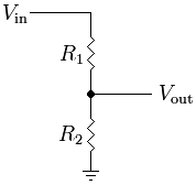
| SGIforever wrote: | Isn't strange that a higher value of the resistor seem to yield a higher voltage for the P14?
Anyway, it looks like I should go for at slightly higher value on the fixed resistor or go for a 50Ohm trim pot.
What happens if the P14 voltage is to low? Less light output (I'm not aiming for a 6 meter screen)? Longer tube life ? |
I guess we have a simple voltage divider. R2 is what we adjust to get 6.35 Vout. Formula, [Vout=(R2)/(R1+R2)]*Vin
So as R2 increases Vout also increases.
| Description: |
|
| Filesize: |
2.71 KB |
| Viewed: |
4464 Time(s) |
|
|
|
| Back to top |
|
|
|
|


