| Author |
Message |
kschmit2
Joined: 09 Mar 2006
Posts: 1141
Location: Heidelberg, Germany
|
| Posted: Fri Apr 04, 2008 5:10 pm Post subject: NEC PG series C.P.C Magnet and ASTIG Adjustment Guide |
|
|
Mechanical Astig Adjustment (C.P.C Magnet Adjustment)
2-pole magnets are those closest to the neckboards, 4-pole magnets (and then 6-pole magnets if present) are closer to the tube bell.
preparatory steps:
- set ASTIG OUTPUT to your installation type (usually: CEILING FRONT). Changing this setting automatically degausses the projector. To get to the ASTIG OUTPUT setting press ADJUST, enter service passcode, go to OPTION, ENTER, ASTIG OUTPUT, ENTER, choose setting
- set ASTIG ADJUSTMENT to ON. You find this setting in the same menu as ASTIG OUTPUT
- switch to the highest combination of refresh rate and resolution that you will later use
- do lens focus as good as possible
- set blue defocus switch to off (deflection board)
- center electronic focus controls
- set electrical focus using the pots on the deflection board
- For core centering you may have to use 100% contrast or enough that you can see it. IIRC you can also lower brightness a bit to put less stress on the phosphor. In any case: make sure you don't take too long if you do it at normal brightness levels and 100% contrast. While the defocussing greatly reduces the chance of burn-ins, you should better be safe than sorry

C.P.C magnet adjustment (look at the dots in the center of the screen for these adjustments)
- use a dot test pattern (either the internal one, or one from a test pattern generator or PC test pattern application)
- take center focus to +100% on the tube that you are working on
- Adjust the 4-pole magnet to make the dot pattern round
- take center focus to -90%
- adjust 2-pole magnet to make the center core of the dot fit the center of the flare
- adjust center focus (using the remote) to best possible focus, i.e. make the flare disappear from the spot.
- adjust edge focus (using the remote, select edges using CTRL + left, right, up or down arrows) to best possible focus
- adjust corner focus (using the remote, select corners using CTRL + left, right, up or down arrows) to best possible focus
- set brightness and contrast back to their normal levels
Note:
the C.P.C Magnet Adjustment has an effect on raster centering (Center Magnet Adjustment), as well as electronic Astig and electrical focus.
So you will have to re-do those, and probably revisit the C.P.C Magnet Adjustment after that again. It really is a back and forth, and only when everything is set up perfectly will your PJ look best.
The end result will be a perfectly round dot.
This is also the reason why we tell users to leave these settings alone, unless they know they are misadjusted.
Electronic Astig Adjustment:
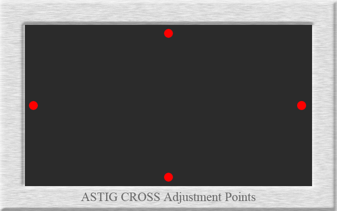
- adjust the ASTIG CROSS (CTL+FOCUS) of the remote control so that the beam is circular at the selected points on the screen (select top, bottom, left and right using CTRL + left, right, up or down arrows).

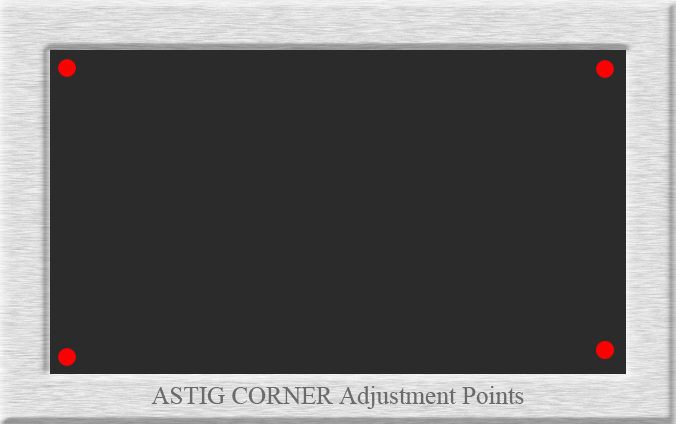
- adjust ASTIG CORNER (CTL+FOCUS to toggle between ASTIG CROSS and ASTIG CORNER) of the remote control so that the beam is circular at the selected points on the screen (upper left corner, upper right corner, lower left conrner, lower right corner using CTRL + left, right, up or down arrows)

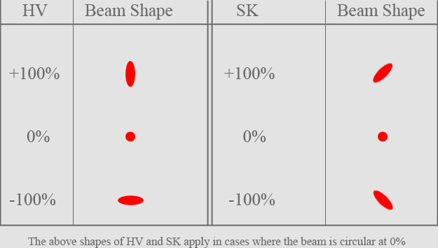
(for reference only) ASTIG Operation:
When ASTIG is selected, test pattern dots are automatically displayed, and the beam is defocussed
ASTIG has two directions of operation, which are displayed as HV and SK on the screen.
When HV and SK are changed, their beams will change as shown below:

Final step:
set Blue defocus switch on the deflection board to ON
Kai
| Description: |
|
| Filesize: |
66.87 KB |
| Viewed: |
10718 Time(s) |
|
| Description: |
|
| Filesize: |
67.04 KB |
| Viewed: |
10718 Time(s) |
|
| Description: |
|
| Filesize: |
13.57 KB |
| Viewed: |
10718 Time(s) |
|
Last edited by kschmit2 on Sat Apr 05, 2008 1:34 pm; edited 3 times in total
|
|
| Back to top |
|
 |
kschmit2
Joined: 09 Mar 2006
Posts: 1141
Location: Heidelberg, Germany
|
| Posted: Fri Apr 04, 2008 5:19 pm Post subject: |
|
|
Please chime in, I'll correct any possible errors.
I would also like to add the necessary info for the XG series, or make a separate guide.
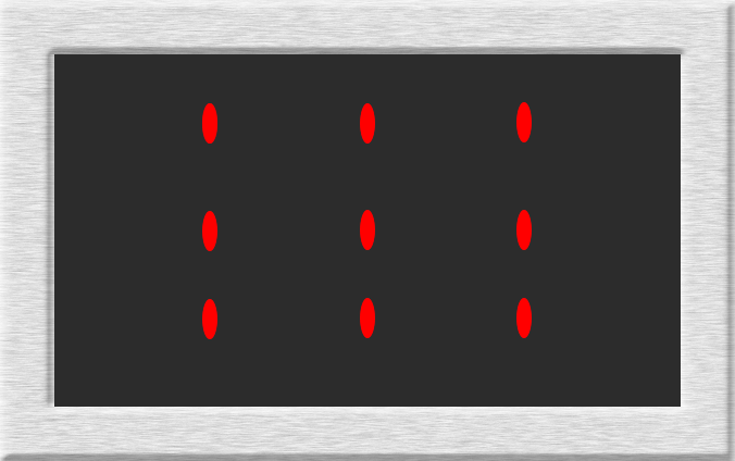
There is an additional preparatory step:
Adjust ASTIG CENTER H/V adjustment control until the top and bottom of the picture look like this:

The XG also has triangularity (6-pole magnets) as an additional step for C.P.C magnet adjustment. That step would be inserted between steps 3 and 4 of C.P.C magnet adjustment.
Also the XG service manual recommends working at 100% contrast with black back raster and each color at bright bias, then 75% contrast and an underfocus state using VR9002. This is slightly confusing, so I didn't want to add that info.
With regard to ASTIG adjustment the XG also has an additional adjustment: ASTIG CENTER (also ASTIG CROSS is called ASTIG EDGE on the XG)
| Description: |
|
| Filesize: |
57.96 KB |
| Viewed: |
10705 Time(s) |
|
|
|
| Back to top |
|
|
jask

Joined: 17 Mar 2006
Posts: 10187
Location: kamloops BC
|
| Posted: Sat Apr 05, 2008 3:45 am Post subject: |
|
|
nice work Kai.
I would add , anyone who is doing this and has any noticeable imbalance to one side or edge should check the physical setup for misalignment.
|
|
| Back to top |
|
|
Bert Randolph
Joined: 03 Jul 2007
Posts: 81
Location: Germany
|
| Posted: Sat Apr 05, 2008 9:22 am Post subject: |
|
|
Kai,
very nice description! I will revisit this thread when I finally have the time to do mech. astig with my XG
Daniel.
|
|
| Back to top |
|
|
hansilili

Joined: 09 Mar 2007
Posts: 302
Location: Köln, Germany
|
| Posted: Sat Apr 05, 2008 5:45 pm Post subject: |
|
|
Hi Kai,
could you please post a screenshot of the round dots in the corners of a PGxtra? I only manage to get more or less even triangles.
Thanks
Hans
_________________
HansA, alles andere ist euer Bier!
|
|
| Back to top |
|
|
kschmit2
Joined: 09 Mar 2006
Posts: 1141
Location: Heidelberg, Germany
|
| Posted: Sat Apr 05, 2008 6:07 pm Post subject: |
|
|
heh, I wish I could
No Xtra in da house 
|
|
| Back to top |
|
|
MikeEby
Joined: 24 Jun 2007
Posts: 5237
Location: Osceola, Indiana
|
| Posted: Sat Apr 05, 2008 6:27 pm Post subject: |
|
|
Nice Job Kai,
Mike
_________________
Doing HD since the last century!
|
|
| Back to top |
|
|
Mark_A_W
Joined: 15 Mar 2006
Posts: 3068
Location: Sunny Melbourne Australia
|
| Posted: Mon Apr 07, 2008 7:10 am Post subject: |
|
|
| hansilili wrote: | Hi Kai,
could you please post a screenshot of the round dots in the corners of a PGxtra? I only manage to get more or less even triangles.
Thanks
Hans |
They are always a bit triangular, usually worse on one side for Red/Blue. The electronic adjustments only do so much...
|
|
| Back to top |
|
|
hansilili
Joined: 09 Mar 2007
Posts: 302
Location: Köln, Germany
|
| Posted: Mon Apr 07, 2008 10:01 am Post subject: |
|
|
| Quote: | hansilili wrote:
Hi Kai,
could you please post a screenshot of the round dots in the corners of a PGxtra? I only manage to get more or less even triangles.
Thanks
Hans
They are always a bit triangular, usually worse on one side for Red/Blue. The electronic adjustments only do so much...
|
I get an error message when trying to choose the blue tube for Electronic Astig correction. Is that known on NEC PGxtras?
_________________
HansA, alles andere ist euer Bier!
|
|
| Back to top |
|
|
kschmit2
Joined: 09 Mar 2006
Posts: 1141
Location: Heidelberg, Germany
|
| Posted: Mon Apr 07, 2008 11:55 am Post subject: |
|
|
|
blue cannot be adjusted electronically, and it isn't really required either, as you have to run it defocussed anyhow
|
|
| Back to top |
|
|
dropzone7

Joined: 12 Jun 2007
Posts: 1069
Location: Charlotte, NC
|
| Posted: Mon Apr 07, 2008 4:28 pm Post subject: |
|
|
Very nice! If I ever get my XG running again I would like to try this.
_________________
"Coffee is for Closers."
|
|
| Back to top |
|
|
kschmit2
Joined: 09 Mar 2006
Posts: 1141
Location: Heidelberg, Germany
|
| Posted: Mon Apr 07, 2008 4:34 pm Post subject: |
|
|
|
I'll have to add updates for the XG first
|
|
| Back to top |
|
|
dbaisey
Joined: 09 Mar 2006
Posts: 821
Location: Southern Cal LA / Seattle WA
|
| Posted: Mon Apr 07, 2008 9:53 pm Post subject: |
|
|
There is a fine line on the mechanical adjustment and if it has all the parts it was intended to have. If your missing the focus alignment sleeve then you will have issues.
If you have the cpc cluster nulled and electronic astig set to 0/0 you should have the egg shape running in the top to bottom direction at screen center. This needs a look at because you can rotate the focus yoke just a bit to make the corrections before starting. The doc 'tube replacement' I think in the advanced set up should cover this. http://www.curtpalme.com/CRT_Tube_Replacement.shtm
Gravity, deflection board swing down tray all play a part in getting it right. The mechanical astig is all about getting the screen center done right AFTER any position and raster centering is done, phase will also have to be perfect and not changed after the initial phase is done. Move the raster you will change the mechanical 2 pole astig the most. Doug
|
|
| Back to top |
|
|
kschmit2
Joined: 09 Mar 2006
Posts: 1141
Location: Heidelberg, Germany
|
| Posted: Tue Apr 08, 2008 6:58 am Post subject: |
|
|
Doug, I'll add the yoke rotation to the guide.
It's mentioned in step 28, fig.1 of the XG Tube Replacement procedure you mentioned (and that's what I refered to in my 2nd post).
But there also is a more in-depth description in the Method of Adjustments section 3.3 (page 10-16) of the XG 751/1101/1351 service manual.
I'm planning to base the steps on that description.
Thanks for chiming in. I really appreciate that.
I'll mention Phase, and the effects of the deflection board swing down tray, as well as the effect the PJs cover will have on the adjustments.
Kai
|
|
| Back to top |
|
|
rickycleung
Joined: 09 Apr 2008
Posts: 55
|
| Posted: Sat Apr 12, 2008 3:40 pm Post subject: |
|
|
Nice work. Any updated on this guide for XG.
Thanks
|
|
| Back to top |
|
|
kschmit2
Joined: 09 Mar 2006
Posts: 1141
Location: Heidelberg, Germany
|
| Posted: Sat Apr 12, 2008 4:58 pm Post subject: |
|
|
give me some time.
Maybe I can do it later tonight or tomorrow
|
|
| Back to top |
|
|
|
|


