 |
Tube/Raster Setup Information
|
(Page 2)
|
Page: 1 2
3
4
5 6 |
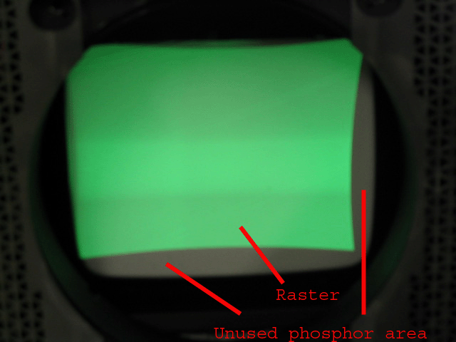
Now, let’s project a raster onto this tube face (see below). What I’ve done here
is turn up the master brightness (G2) controls so that the RASTER area is lit up
completely. The raster of a tube face is the area that the scanning electron
beam covers, and if I turn up the internal master brightness control, you can
see this area. Note that there are areas of the tube that are not being used by
the raster. What you want to do is to use as much of the tube phosphor as
possible when setting up the projector without shooting off of the face of the
tube.

Still referring to the above image, you can see that the raster area is shifted
up and to the left of the tube face. This is NOT a good way to set up an image
on the face of a tube. What is happening on the left edge of the tube phosphor
is the raster is shooting off of the side of the tube. This causes the electron
beam to shoot onto the edge of the glass face where there is no cooling fluid,
and the strong electron beam will generate heat off of the face of the tube.
Since this area on the edge is not cooled by the cooling fluid, it is possible
to overheat the glass, and the tube can implode.

|
|


