Definitive CRT Projector Setup Guide |
(Page 2)
|
Page:
1 2
3 4
5 6
|
| |
Lens Toe In
Once the raster centering is complete, you’re ready to do the lens ‘toe in’.
I get a LOT of emails about this. Depending on the screen size that you’re
projecting onto, the red and blue lens/tube angle will need to be changed so
that the images overlap with minimum convergence adjustment. The green tube is
always your reference, and should be centered left to right on the screen,
aiming at the middle of the screen. If your projector is set slightly cockeyed
to the screen, you will not get a perfectly square image. Accuracy counts when
installing a projector!
The vast majority of projectors have a similar toe-in method to the NEC
shown:
There are two screws or bolts that hold the top of the tube frame into place.
Loosen these bolts, but don’t remove them. Also loosen the bottom tube bolts
that hold the bottom of the tube/lens assembly in place.
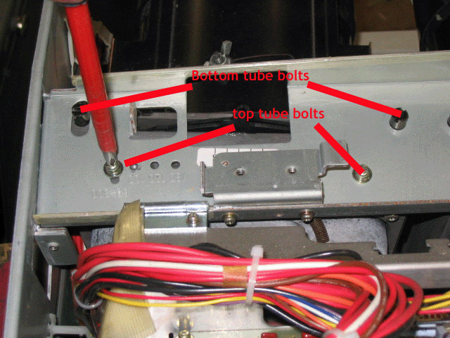
When the 4 bolts are loose, the tube/lens assembly will now swivel back and
forth a few degrees. Firmly grasp the lens from the front and the tube will
swivel side to side along with the lens.

See the below pix to see how the R and B tubes will travel side to side:
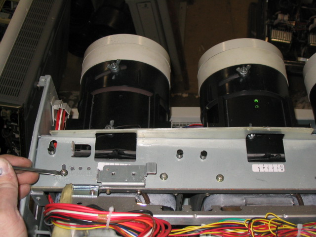
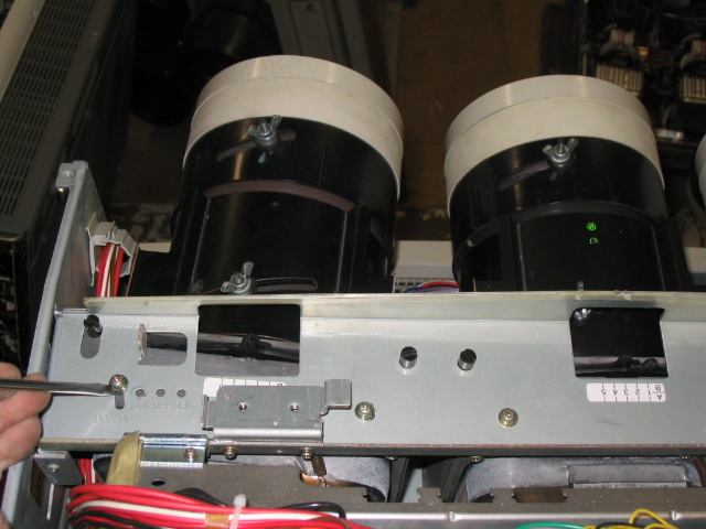
This left/right movement will drastically change the left/right position of
the red and blue images as compared to the green. The lens toe-in will ONLY
affect the HORIZONTAL position of the image, not the up/down (vertical) image of
the red, blue and green tubes.
Everything should now be in focus, but your crosshairs will be slightly out
of whack.
To get the correct lens toe-in for each lens, put up the crosshair pattern:
The green tube vertical line should be in the middle of the screen, as should
the horizontal line. If the horizontal line isn’t in the middle of the screen,
loosen the ceiling bracket of the projector and tilt the projector so that it
is. If the projector is floor mounted, shim the projector front or back so that
the entire green image is centered.
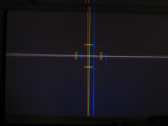
Using the lens toe-in method, move the R and B lens left and right so that
the vertical lines are completely overlapped. In order to overlap the horizontal
lines, use the ‘raster shift’ in the ‘ref adjust’ menu to shift the vertical
image of the tubes that need correction. It’s somewhat irrelevant whether you
shift the R, G or B images. The final result will be the following:

The three images are now overlapped in the dead center of the screen, but the
rest of the image will be out of alignment. So far so good!
You’ll also notice that the NEC chassis is VERY prone to shifting convergence
slightly if the covers are off. This is thanks to the thin sheet metal that NEC
used throughout the construction. The ‘position’ control will compensate for
slight shifts of the raster due to the chassis shifting. Do the final
adjustments with all covers of the NEC in place!
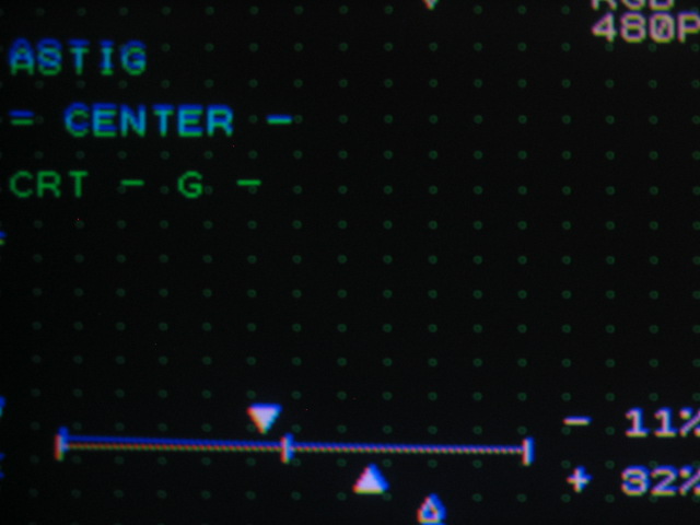
Electronic Astig adjustment
Setting the electronic astig adjustments isn’t too difficult on an NEC, but
again, you need to understand what astig does to properly adjust the settings.
(my poor picture taking skills don’t help either, but this should get the point
across).
Astigmatism is defined as the roundness of a dot that is displayed on the
face of the tube. The rounded the dot, the better the overall focus will be on
the face of the tube. You’ll note that the set automatically goes into the dot
mode when you enter the astig mode, and the dots are defocused slightly. That
enables you to adjust the astig settings to get a round dot more easily. Shown
below are what you should see when the astig settings are properly set:
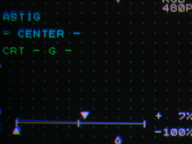
The series of photos below show what mis-adjustments of the astig settings
will do. Notice that the round dot shape will turn into a series of ovals, the
direction of which will depend on how the astig settings are set.
Vertical ovals:
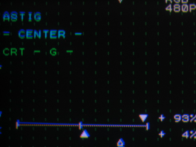
Horizontal ovals:
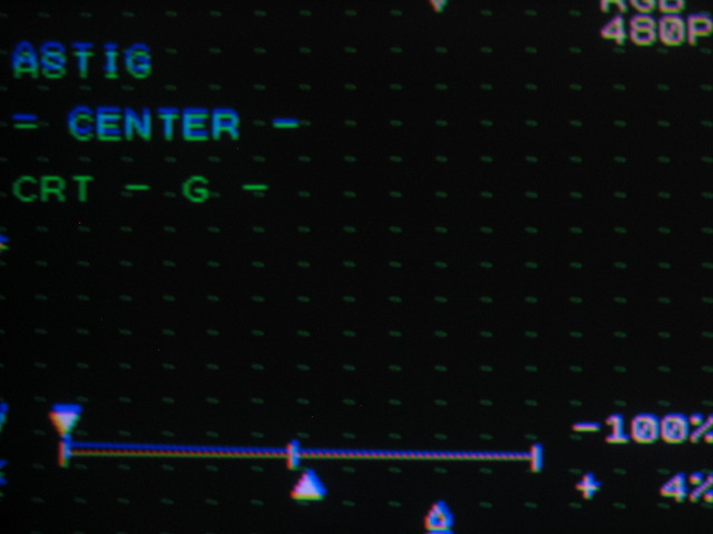
Diagonal ovals:
If you look carefully at the below oval, you’ll see a dark core in the middle
of each dot. This shows that the core of the displayed dot is properly centered,
indicating that the mechanical astig magnets on the neck of the tube are
properly set and that the electronic astig is correctly set as well.
Adjustments of the edge and corner astig are done in a similar manner to the
above, but you’ll find that the edges have far less adjustment range than the
center of the screen. This is normal. Set each astig setting for the roundest
dots that you can get for each color.

|
