 |
||||||||||||
| Home |
|
Products For Sale |
FAQs, Tips, Manuals |
Referral List |
|
Photo Gallery |
|
Links |
|
Contact Us |
|
|
||||||||||||||||
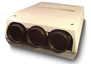
I’ll do some basic dissection of the Barco 600 chassis here, as it’s one of the more popular sets of the analog convergence era. I still stock some parts for these, but I am not selling a lot of these sets any more due to age related parts failure. I will assume for this write-up that you have the manual that outlines the proper setup of these older projectors. As of this writing, several of the analog manuals are available for download on the site. While your exact model might not be listed, download a few of the analog manuals and I’m sure you’ll figure yours out. Note: All LED’s in Barcos are color coded. Green = good and indicate a normal operating condition. Overview Here’s a picture of the left side of the chassis. Despite the age of this set, you can see that Barco held true to the basic layout of a Barco chassis for many years. Sets right up to about 1999 were similar in layout to the below. With these older models of projectors, there were many different versions of the chassis, and as with later Barcos, the 761XXX module numbers must match up to ensure that replacement boards will work in a set. Even though two modules may look identical, Barco put in minor sneaky changes, so that mismatching board numbers usually will not work in a set, despite the modules looking identical. Some boards might partially work, most of them will not.
The far left board is the H shift board. It controls the horizontal raster position of each tube with the trimpots along the top edge of the board. Three trimpots towards the CRT area of the board control various keystone and pincushion of each tube. The second board from the left is the H output board and HV section. The quadrupler and HV shield are not shown on the above image, the HV quadrupler usually is located to the left of the left fan shown above. The HV output leads of the quadrupler then snake under the chassis to the HV splitter and to the focus board. The third board from the left is the vertical board. Depending on your set, the V board will look different from the picture above. The two small boards next to the V board are the RGB input boards and the test pattern generator boards. These boards have few components on them and rarely fail. There are two styles of video and RGB boards in the various Barco chassis, and each style of board will have several different versions. One board is an RGB only board. It only contains the circuitry required to process the RGB input signal, and the composite video signal dead-ends at this board. The other style of board incorporates a quad decoder (video processor) as well as the RGB circuitry onto one board. The back of the set will then have the video and RGB inputs live as selected by the little wired remote on the back of the set. SMPS- the switch mode power supply is similar to later Barco models, but this SMPS is of an older design. As with other Barco sets, failure of the SMPS is fairly common as it is driven hard.
In addition to the SMPS, there are the main AC input board and focus/diagnostic boards on the right side of the set. The AC input board is similar to later models.
|
|
|||||||||||||||


© Copyright CurtPalme.com. All Rights Reserved. |